4.4. Absolute stability#
We have seen that a necessary condition for stability of a method is that the local truncation errors must not grow from one step to the next.
Consider the test equation \(y' = \lambda y\), the numerical solution satisfies
After \(n\) steps
Therefore, any perturbations, rounding errors, or local truncation errors are multiplied by approximately \(R(z)^n\). To prevent these disturbances from growing, we require
which provides the definition of absolute stability.
Definition 4.6 (Absolute stability)
A method is considered to be absolutely stable for a particular value of \(z\) if
Since \(z = h \lambda\), changing the step size \(h\) will change \(R(z)\) and therefore a method may be stable for some values of \(h\) and unstable for others. Absolute stability therefore determines which step sizes can be used safely.
4.4.1. Region of absolute stability#
Of course we require our methods to be stable, so it is useful to know for what values of \(h\) we have a stable method. This gives the definition of the region of absolute stability.
Definition 4.7 (Region of absolute stability)
The region of absolute stability is the subset of the complex plane that satisfies
The boundary of the stability region is given by
Inside the boundary the method is stable, while outside it is unstable.
For example, consider the stabiltiy function for the Euler method which is
therefore the stability region is
Let \(z = x + iy\) then
The equation of a circle is
so the stability region of the Euler method is a circle of radius 1 centred at \((-1, 0)\).
The region of absolute stability for the Euler method is shown in Fig. 4.2.
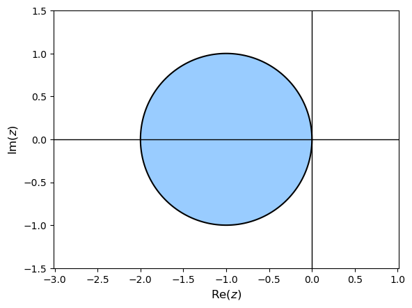
Fig. 4.2 The region of absolute stability for the Euler method.#
The size and shape of the stability region provide important measures of the performance of a numerical method. In particular, when solving stiff equations we seek methods whose stability regions contain a large portion of the left half-plane.
4.4.2. Interval of absolute stability#
The interval of absolute stability is the portion of the real axis that liess inside the region of absolute stability.
Definition 4.8 (Interval of absolute stability)
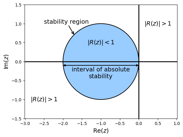
Fig. 4.3 Interval of absolute stability for the Euler method.#
We saw above that the region of absolute stability for the Euler method is a unit circle centred at \((-1,0)\), so the region of absolute stability is
Since \(z = h\lambda\) then
So the Euler method is stable for the test equation \(y' = \lambda y\) using a step length \(h \leq \dfrac{2}{|\lambda|}\).
Consider the solution to the ODE \(y' = -15y\) that we saw earlier in this chapter.
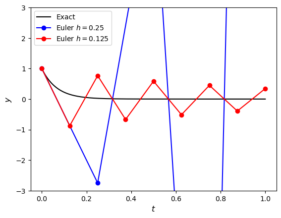
Fig. 4.4 Solutions to the initial value problem \(y' = -15y\), \(t\in [0, 1]\) and \(y(0) = 1\) using the Euler method with \(h=0.25\) and \(h=0.125\).#
Here \(\lambda = -15\) so the stability interval for the Euler method is
So \(h = 0.25\) is outside the stability interval and results in an unstable solution whereas \(h = 0.125\) is inside the stability interval and results in a stable (albeit oscillatory) solution.
4.4.3. Plotting stability regions#
We can plot the region of absolute stability by generate a set of points for \(z\) in the complex plane and plot the contour where \(|R(z)| = 1\) which is the boundary of the stability region. The code for producing a plot of the region of absolute stability of the Euler method using Python is shown below.
import numpy as np
import matplotlib.pyplot as plt

# Generate z values
xmin, xmax, ymin, ymax = -3, 1, -1.5, 1.5
X, Y = np.meshgrid(np.linspace(xmin, xmax, 200),np.linspace(ymin, ymax, 200))
Z = X + Y * 1j

# Define stability function
R = 1 + Z

# Plot stability region
fig = plt.figure()
contour = plt.contourf(X, Y, abs(R), levels=[0, 1], colors="#99ccff")  # Plot stability region
plt.contour(X, Y, abs(R), colors= "k", levels=[0, 1])                  # Add outline
plt.axhline(0, color="k", linewidth=1)                                 # Add x-axis line
plt.axvline(0, color="k", linewidth=1)                                 # Add y-axis line

plt.axis("equal")
plt.axis([xmin, xmax, ymin, ymax])
plt.xlabel("$\mathrm{Re}(z)$", fontsize=12)
plt.ylabel("$\mathrm{Im}(z)$", fontsize=12)
plt.show()
% Generate z values
xmin = -3;
xmax = 1;
ymin = -1.5;
ymax = 1.5;
[X, Y] = meshgrid(linspace(xmin, xmax, 200), linspace(ymin, ymax, 200));
Z = X + Y * 1i;

% Define stability function
R = 1 + Z;

% Plot stability region
contourf(X, Y, abs(R), [0, 1], LineWidth=2)
xline(0, LineWidth=2)
yline(0, LineWidth=2)

colormap([153, 204, 255 ; 255, 255, 255] / 255)
axis equal
axis([xmin, xmax, ymin, ymax])
xlabel("$\mathrm{Re}(z)$", FontSize=12, Interpreter="latex")
ylabel("$\mathrm{Im}(z)$", FontSize=12, Interpreter="latex")