8. Lighting#
In this lab we will be looking at adding a basic lighting model to our application. Lighting modelling is in itself a huge topic within the field of computer graphics and modern games and movies can look very lifelike thanks to some very clever techniques. Lighting models come in two main types: local illumination and global illumination:
local illumination – the colour and brightness of individual points on a surface are determined by the light emanating from one or more light sources.
global illumination – the colour and brightness of individual points on a surface are determine both by the light emanating from light sources in addition to light that is reflected off of other objects in the scene.

Here we will be applying a local illumination model since they are easier to apply than global illumination and quicker to compute. The downside is that they don’t produce a rendering as realistic than with global illumination.
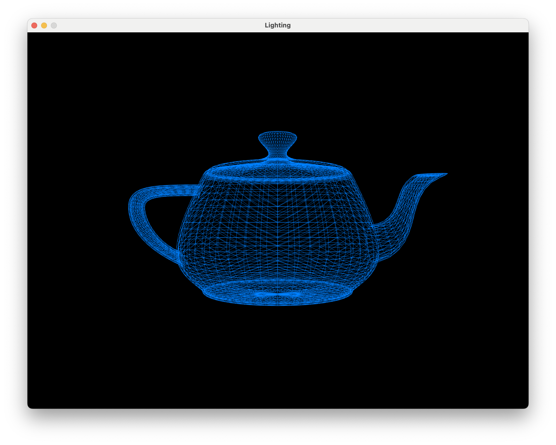
Compile and run the Lab08_Lighting project and you will see the window below showing a wire frame representation of the Utah teapot.
Note
The Utah teapot is a standard test model for computer graphics first created in 1975 by Martin Newell whilst at the University of Utah. It has become a bit of an in-joke in the computer graphics community and has appeared in Pixar’s Toy Story and in The Simpsons episode Treehouse of Horror VI.
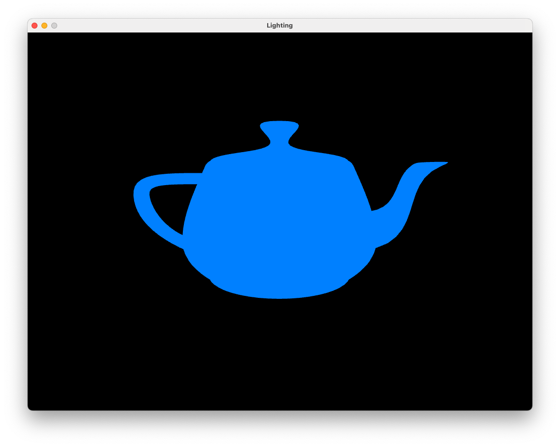
The teapot has been rendered as a wire frame model since in the absence of light and shadow we wouldn’t be able to tell that it was in fact a 3D model. We can turn of the wire frame rendering by commenting out the line glPolygonMode(GL_FRONT_AND_BACK, GL_LINE);. Do this and you should see the following.
8.1. The Model class#
If you take a look at the source code in the Lab08_Lighting you will notice that in addition to the classes introduced in previous labs (Texture, Shader and Camera) we have an addition class called Model which is defined in the model.hpp and model.cpp files. The Model class has been written so that we can load the vertex and texture co-ordinates from external files rather than having to define these in our code. Take a look at the Lab08_Lighting.cpp file where the following Model class methods have been called:
Line 89:
Model teapot("../assets/teapot.obj)– this is the constructor for the Model class and creates an object calledteapot, loads the vertex and texture co-ordinates from an .obj file (see below) and creates the relevant buffers.Line 92:
teapot.addTexture("../assets/blue.bmp", "diffuse");– this method loads a texture map calledblue.bmpand sets its type todiffuse.Line 131:
teapot.draw(shaderID)- this method binds the buffers objects and instructs OpenGL to draw the model
8.1.1. Wavefront (.obj) files#
The Model class includes a private member function called loadObj() written by contributors of opengl-tutorial.org which loads in a wavefront (.obj) file. A wavefront file is one of the many different types of file that is used to describe 3D models in computer graphics. In the assets/ folder you will see some files with the extension .obj. Open the file cube.obj using a text editor and you will see the following.
# Blender 4.0.2
# www.blender.org
mtllib cube.mtl
o Cube
v 1.000000 1.000000 -1.000000
v 1.000000 -1.000000 -1.000000
v 1.000000 1.000000 1.000000
v 1.000000 -1.000000 1.000000
v -1.000000 1.000000 -1.000000
v -1.000000 -1.000000 -1.000000
v -1.000000 1.000000 1.000000
v -1.000000 -1.000000 1.000000
vn -0.0000 1.0000 -0.0000
vn -0.0000 -0.0000 1.0000
vn -1.0000 -0.0000 -0.0000
vn -0.0000 -1.0000 -0.0000
vn 1.0000 -0.0000 -0.0000
vn -0.0000 -0.0000 -1.0000
vt 0.875000 0.500000
vt 0.625000 0.750000
vt 0.625000 0.500000
vt 0.375000 0.990255
vt 0.375000 0.750000
vt 0.625000 0.008121
vt 0.375000 0.250000
vt 0.375000 0.008121
vt 0.375000 0.500000
vt 0.125000 0.750000
vt 0.125000 0.500000
vt 0.625000 0.250000
vt 0.875000 0.750000
vt 0.625000 0.988631
s 0
usemtl Material
f 5/1/1 3/2/1 1/3/1
f 3/2/2 8/4/2 4/5/2
f 7/6/3 6/7/3 8/8/3
f 2/9/4 8/10/4 6/11/4
f 1/3/5 4/5/5 2/9/5
f 5/12/6 2/9/6 6/7/6
f 5/1/1 7/13/1 3/2/1
f 3/2/2 7/14/2 8/4/2
f 7/6/3 5/12/3 6/7/3
f 2/9/4 4/5/4 8/10/4
f 1/3/5 3/2/5 4/5/5
f 5/12/6 1/3/6 2/9/6
The vertex and face data is given in lines with the following abbreviations:
v– the \((x, y, z)\) co-ordinates of a vertexvn– the \((n_x, n_y, n_z)\) normal vector for the vertexvt– the \((u, v)\) texture co-ordinatesf– indices of the vertices of a face. Each face is defined by 3 vertices so we have 3 sets of 3 values. The face vertices are of the formv/vt/vnso3/2/1refers to a vertex where the co-ordinates are given by the 3rdvline, the texture co-ordinates are given by the 2ndvtline and the normal vector is given by the 1stvnline.
Note
The loadObj() private member function in the Model class is quite simplistic and we need to make sure our .obj file is in the correct form. There are some model loading libraries available such as assimp (open ASSet IMPorter library) that can handle most common object formats but use of this requires compiling source code and configuring the IDE which is a bit too fiddly for what we are doing here.
To see how you can use Blender to create .obj files see below.
8.2. Phong’s lighting model#
Phong’s lighting model first described by Bui Tuong Phong is a local illumination model that simulates the interaction of light falling on surfaces. The brightness of a point on a surface is based on three components
ambient reflection – a simplified model of light that reflects off all objects in a scene
diffuse reflection – describes the direct illumination of a surface by a light source based on the angle between the light source direction and the normal vector to the surface
specular reflection – models the shiny highlights on a surface caused by a light source based on the angle between the light source direction, the normal vector and the view direction
The colour intensity of a fragment on the surface is calculated as a sum of these components, i.e.,
where theses are 3-element vectors of RGB colour values.
8.2.1. Ambient reflection#
Ambient reflection is light that is scatters off of all surfaces in a scene. To model this we simply assume that the object emits some light. The equation to do this is
where \(k_a\) is known as the ambient reflection constant which takes on a value between 0 and 1 and \(\mathbf{O}_d\) is the object colour. \(k_a\) is a property of the object so we specify a value for this for each objects in our scene. Add the following code to the Lab08_Lighting.cpp file just before the render loop.
// Define teapot object lighting properties
teapot.ka = 0.2f;
All of the lighting calculations will be performed by the shaders so we need to send the ambient constant to the fragment shader using a uniform. In the render loop add the following code after we activate the shader.
// Send light source properties to the shader
glUniform1f (glGetUniformLocation(shaderID, "ka"), teapot.ka);
Then edit fragmentShader.glsl to add the uniform for the ambient constant and use it calculate ambient lighting.
#version 330 core

// Inputs
in vec2 UV;
in vec3 fragmentPosition;
in vec3 normal;

// Output
out vec3 fragmentColour;

// Uniforms
uniform sampler2D diffuseMap;
uniform float ka;

void main()
{
    // Object colour
    vec3 objectColour = vec3(texture(diffuseMap, UV));

    // Ambient reflection
    vec3 ambient = ka * objectColour;

    // Fragment colour
    fragmentColour = ambient;
}
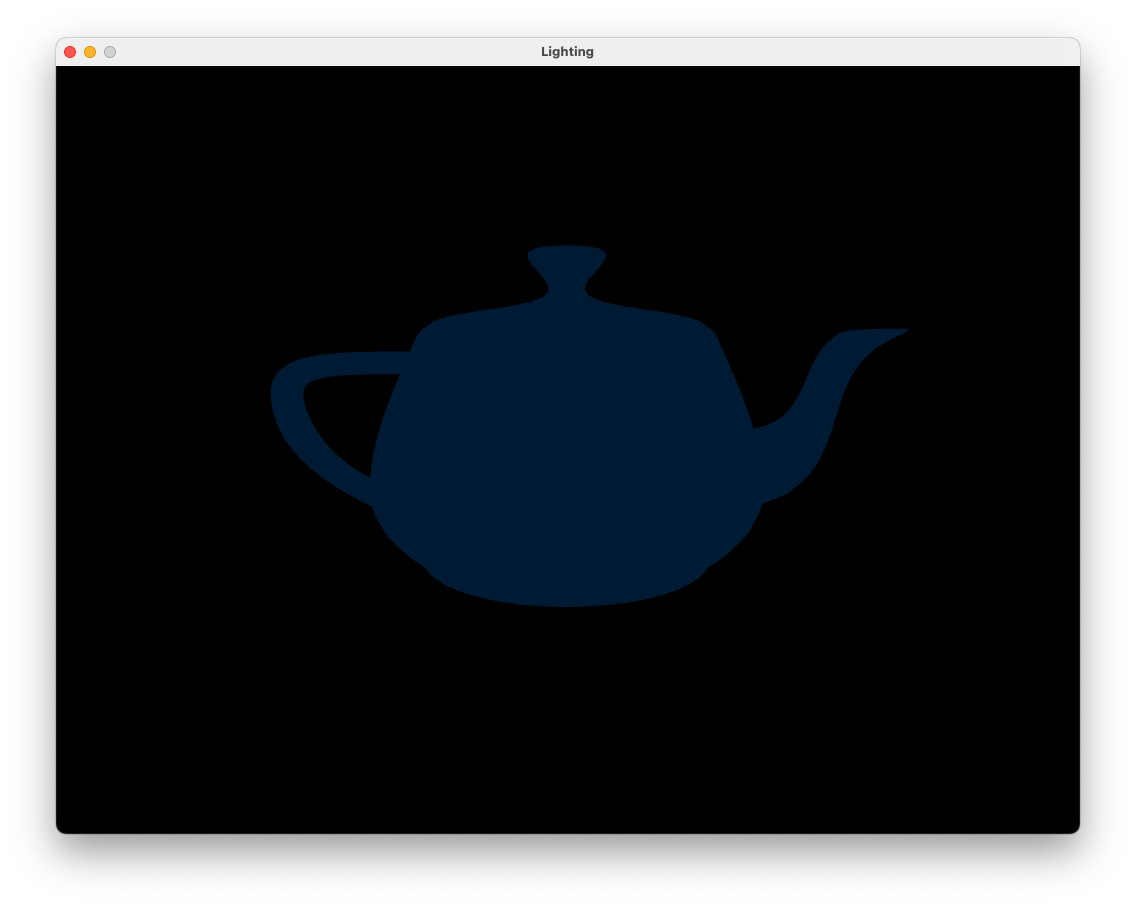
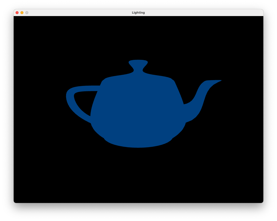
Changing the value of \(k_a\) will make the colour of the teapot lighter or darker.

8.2.2. Diffuse reflection#
Diffuse reflection is the reflection of light off a rough surface. Consider Fig. 8.4 that shows parallel light rays hitting a surface where light is scattered in multiple directions.

Fig. 8.4 Light rays hitting a rough surface are scattered in all directions.#
To model diffuse reflection we assume that light is reflected equally in all directions (Fig. 8.5).

Fig. 8.5 Diffuse reflection scatters light equally in all directions.#
The amount of light that is reflected to the viewer is modelled using the angle \(\theta\) between the light vector \(\mathbf{L}\) which points from the fragment to the light source and the normal vector \(\mathbf{n}\) which points perpendicular to the surface. If \(\theta\) is small then the light source is directly in front of the surface so most of the light will be reflected to the viewer. Whereas if \(\theta\) is close to 90\(^\circ\) then the light source is nearly in line with the surface and little of the light will be reflected to the viewer. When \(\theta > 90^\circ\) the light source is behind the surface so no light is reflected to the viewer. We model this using \(\cos(\theta)\) since \(\cos(0^\circ) = 1\) and \(\cos(90^\circ)=0\). Diffuse reflection is calculated using
where \(k_d\) is known as the diffuse reflection constant which takes a value between 0 and 1, and \(\mathbf{I}_p\) is the colour intensity of the point light source. Recall that the angle between two vectors is related by dot product so if the \(\mathbf{L}\) and \(\mathbf{n}\) vectors are unit vectors then \(\cos(\theta) = \mathbf{L} \cdot \mathbf{n}\). If \(\theta > 90^\circ\) then light source is behind the surface and no light should be reflected to the viewer. When \(\theta\) is between 90\(^\circ\) and 180\(^\circ\), \(\cos(\theta)\) is negative so we limit the value of \(\cos(\theta )\) to positive values
Like the ambient constant, the diffuse constant is a property of the object. Set the diffuse constant for our teapot by adding the following code where we defined the ambient constant
teapot.kd = 0.7f;
and add the following after where we defined the object properties
// Define light source properties
glm::vec3 lightPosition = glm::vec3(2.0f, 2.0f, 2.0f);
glm::vec3 lightColour   = glm::vec3(1.0f, 1.0f, 1.0f);
Here we have defined a point light source positioned at \((2, 2, 2)\) in the world space and has a colour of white since the RGB values are \((1, 1, 1)\).
All calculations performed in the fragment shader is done in the screen space so the vertex shader outputs gl_Position which is the screen space vertex co-ordinates. However, we want to perform lighting calculations in the view space so we also need to calculate the view space co-ordinates of the object vertices and of the light source position. For the vertices we calculate the \(MV\) matrix that transforms from the model space to the view space
and pass this, along with the view matrix for transforming the light source position to the view space, to the vertex shader using uniforms. Add the following code after the \(MV\!P\) matrix is sent to the shader.
// Send MV and view matrices to the vertex shader
glm::mat4 MV = camera.view * model;
glUniformMatrix4fv(glGetUniformLocation(shaderID, "MV"), 1, GL_FALSE, &MV[0][0]);
Now add the following code just after we send the colour of the ambient light to the shader to do the same for the diffuse light constant, colour and view space position.
glUniform1f (glGetUniformLocation(shaderID, "kd"), teapot.kd);
glUniform3fv(glGetUniformLocation(shaderID, "lightColour"), 1, &lightColour[0]);
glm::vec3 viewSpaceLightPosition = glm::vec3(camera.view * glm::vec4(lightPosition, 1.0f));
glUniform3fv(glGetUniformLocation(shaderID, "lightPosition"), 1, &viewSpaceLightPosition[0]);
OpenGL interpolates the outputs from the vertex shader and passes the interpolated values for each fragment to the fragment shader so we calculate view space versions of the fragment position, normal vector and light source positions in the vertex shader. The view space fragment position is calculated by multiplying the vertex position by the \(MV\) matrix, however the view space normal vector is calculated using the following transformation
Recall that \(A^\mathsf{T}\) is the transpose and \(A^{-1}\) is the inverse of the matrix \(A\). We use this transformation to ensure that the normal vector is perpendicular to the surface after the object vertices have been multiplied by the \(MV\) matrix. If you are interested in the derivation of this transformation, click on the dropdown link below.
Derivation of the view space normal transformation
Consider the diagram in Fig. 8.6 that shows the normal and tangent vectors to a surface in the object space. If the combined model and view transformations preserves the scaling of the edge such the equal scaling is used in the \(x\), \(y\) and \(z\) axes then the normal and tangent vectors are perpendicular in the view space.

Fig. 8.6 Normal and tangent vectors in the object space.#
If the model and view transformations do not preserve the scaling then the the view space normal vector is no longer perpendicular to the tangent vector (Fig. 8.7).

Fig. 8.7 Normal and tangent vectors in the view space.#
We need to derive a transformation matrix \(A\) that transforms the object space normal vector \(\mathbf{n}\) to the view space normal vector \(\mathbf{n}_{view}\) such that it is perpendicular to the view space tangent vector \(\mathbf{T}_{view}\). The view space normal and tangent vectors are calculated using
The dot product between two perpendicular vectors is zero, so
We can replace the dot product by a matrix multiplication by transposing \(A \mathbf{n}\)
A property of matrix multiplication is that the transpose of a multiplication is equal to the multiplication of the transposes swapped (i.e., \((AB)^\mathsf{T} = B^\mathsf{T} A^\mathsf{T}\)) so we can write this as
If \(A^\mathsf{T} MV = I\) then the view space normal and tangent vectors are perpendicular. Solving for \(A\) gives
The matrix \((MV^{-1})^\mathsf{T}\) is the transformation matrix to transform the object space normal vectors to the view space that ensures the view space normal vectors are perpendicular to the surface.
Edit the vertex shader so that is looks like the following.
#version 330 core

// Inputs
layout(location = 0) in vec3 position;
layout(location = 1) in vec2 uv;
layout(location = 2) in vec3 normal;

// Outputs
out vec3 fragmentPosition;
out vec2 UV;
out vec3 Normal;

// Uniforms
uniform mat4 MVP;
uniform mat4 MV;

void main()
{
    // Output vertex position
    gl_Position = MVP * vec4(position, 1.0);

    // Output texture co-ordinates
    UV = uv;

    // Output view space fragment position and normal vector
    fragmentPosition = vec3(MV * vec4(position, 1.0));
    Normal           = mat3(transpose(inverse(MV))) * normal;
}
Here we use the \(MV\) matrix to calculate the view space fragment position and use the transformation from equation (8.3) to calculate the normal vector in the view space.
In the fragment shader we need to input the view space fragment position and the normal vector outputted by the vertex shader as well as declaring the uniforms for the diffuse constant, light source position and colour. Edit the fragment shader so that it looks like the following.
#version 330 core

// Inputs
in vec2 UV;
in vec3 fragmentPosition;
in vec3 Normal;

// Output
out vec3 fragmentColour;

// Uniforms
uniform sampler2D diffuseMap;
uniform float ka;
uniform float kd;
uniform vec3 lightColour;
uniform vec3 lightPosition;

void main()
{
    // Object colour
    vec3 objectColour = vec3(texture(diffuseMap, UV));

    // Ambient reflection
    vec3 ambient = ka * objectColour;

    // Diffuse reflection
    vec3 light     = normalize(lightPosition - fragmentPosition);
    vec3 normal    = normalize(Normal);
    float cosTheta = max(dot(normal, light), 0);
    vec3 diffuse   = kd * lightColour * objectColour * cosTheta;

    // Calculate fragment colour
    fragmentColour = ambient + diffuse;
}
Here we have added code to calculate diffuse reflection using equation (8.2). Compile and run the program and you should see the result of applying ambient and diffuse reflection to the teapot as shown in Fig. 8.8.
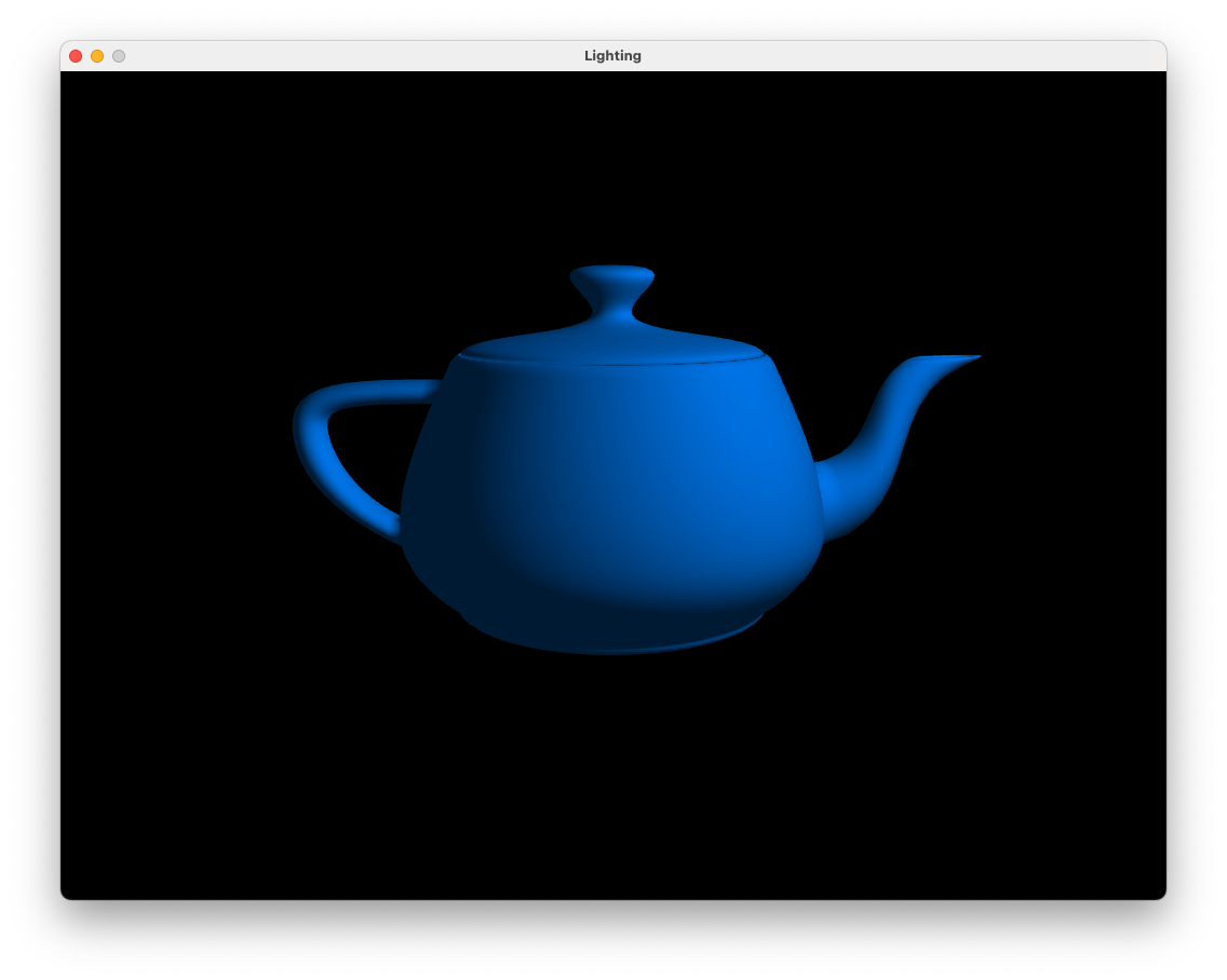
Fig. 8.8 Ambient and diffuse reflection: \(k_a = 0.2\), \(k_d = 0.7\).#
We now have visual cues as to the geometry of the teapot. Use the keyboard and mouse to view the teapot from different angles. You will notice that the side of the teapot facing away from the light source is darker since the angle between the normal vectors and the light source vector is larger.
8.2.3. Specular reflection#
Consider Fig. 8.9 that shows parallel light rays hitting a smooth surface where the reflected rays will point mostly in the same direction (think of a mirrored surface).

Fig. 8.9 Light rays hitting a smooth surface are reflected in the same direction.#
Specular reflection depends upon the position of the light source and the fragment in the view space. Consider Fig. 8.10 that shows a surface with a normal vector \(\mathbf{n}\), a vector \(\mathbf{L}\) pointing from the surface to a light source and a vector \(\mathbf{R}\) pointing in the direction of reflected light off the surface. The angle between \(\mathbf{L}\) and \(\mathbf{n}\), \(\theta\) which is known as the incidence angle, and the angle between \(\mathbf{R}\) and \(\mathbf{n}\) are the same.

Fig. 8.10 The light vector is reflected about the normal vector.#
If \(\mathbf{n}\) and \(\mathbf{L}\) are unit vectors then the \(\mathbf{R}\) vector is calculated using
If you are interested in the derivation of this formula, click on the dropdown below.
Derivation of the reflection vector
The vector projection of a vector \(\mathbf{a}\) onto another vector \(\mathbf{b}\) is the vector \(\operatorname{proj}_\mathbf{b} \mathbf{a}\) that points in the same direction as \(\mathbf{b}\) with a length that is equal to the adjacent side of a right-angled triangle where \(\mathbf{a}\) is the hypotenuse and the vector \(\operatorname{proj}_\mathbf{b} \mathbf{a}\) is the adjacent side Fig. 8.11.

Fig. 8.11 The projection of \(\mathbf{a}\) onto \(\mathbf{b}\).#
\(\operatorname{proj}_\mathbf{b} \mathbf{a}\) is represented by the green vector in Fig. 8.11 and is calculated by multiplying the unit vector \(\hat{\mathbf{b}}\) by the length of the adjacent side of the right-angled triangle. Using trigonometry this gives
Recall that the geometric definition of the dot product is
which can be rearranged to
so
Consider Fig. 8.12 that shows a surface with a normal vector \(\mathbf{n}\), a light source vector \(\mathbf{L}\) and a reflection vector \(\mathbf{R}\).

Fig. 8.12 Calculating the reflection vector \(\mathbf{R}\).#
If \(\mathbf{n}\) and \(\mathbf{L}\) are unit vectors, then the reflection vector \(\mathbf{R}\) can be calculated by reversing \(\mathbf{L}\) and adding two projections \((\mathbf{L} \cdot \mathbf{n}) \mathbf{n}\) to it
For a perfectly smooth surface the reflected ray will point in the direction of the \(\mathbf{R}\) vector so in order to see the light the viewer would need to be positioned in the direction of the \(\mathbf{R}\) vector. The position of the camera is represented by the \(\mathbf{camera}\) vector which points from the fragment to the camera (which is at \((0,0,0)\) in the view space). Since most surfaces are not perfectly smooth we add a bit of scattering to the model the amount of specular reflection seen by the viewer. This is determined by the angle \(\alpha\) between the \(\mathbf{R}\) vector and the \(\mathbf{camera}\) vector. The closer the camera vector is to the reflection vector, the smaller the value of \(\alpha\) will be and the more of the light will be reflected towards the camera.

Fig. 8.13 Specular reflection scatters light mainly towards the reflection vector.#
Phong modelled the scattering of the reflected light rays using \(\cos(\alpha)\) raised to a power
where \(k_s\) is the specular reflection constant similar to its ambient and diffuse counterparts and \(N_s\) is the specular exponent that determines the size of the specular highlights. If \(\mathbf{R}\) and \(\mathbf{camera}\) are unit vectors, then \(\cos(\alpha)\) can be calculated using the dot product between the \(\mathbf{R}\) and \(\mathbf{camera}\) vector limited to positive values
In the Lab08_Lighting.cpp file, specify the following values for the specular constant and exponent
teapot.ks = 1.0f;
teapot.Ns = 20.0f;
and send the specular light source constant and exponent to the shader where we did this for the ambient and diffuse colours.
glUniform1f(glGetUniformLocation(shaderID, "ks"), teapot.ks);
glUniform1f(glGetUniformLocation(shaderID, "Ns"), teapot.Ns);
In the fragment shader add uniforms for the specular light source values
uniform float ks;
uniform float Ns;
and in the main() function add specular refection to our teapot.
// Specular reflection
vec3 camera     = normalize(-fragmentPosition);
vec3 reflection = - light + 2 * dot(light, normal) * normal;
float cosAlpha  = max(dot(camera, reflection), 0);
vec3 specular   = ks * lightColour * pow(cosAlpha, Ns);
Here we calculate the \(\mathbf{camera}\) and \(\mathbf{R}\) vectors before calculating the specular reflection using equation (8.4) (the pow(x, y) function calculates \(x^y\)). Now we just need to add the specular reflection to the fragment colour.
// Fragment colour
fragmentColour = ambient + diffuse + specular;
Compile and run your program and you should see the image shown in Fig. 8.14.
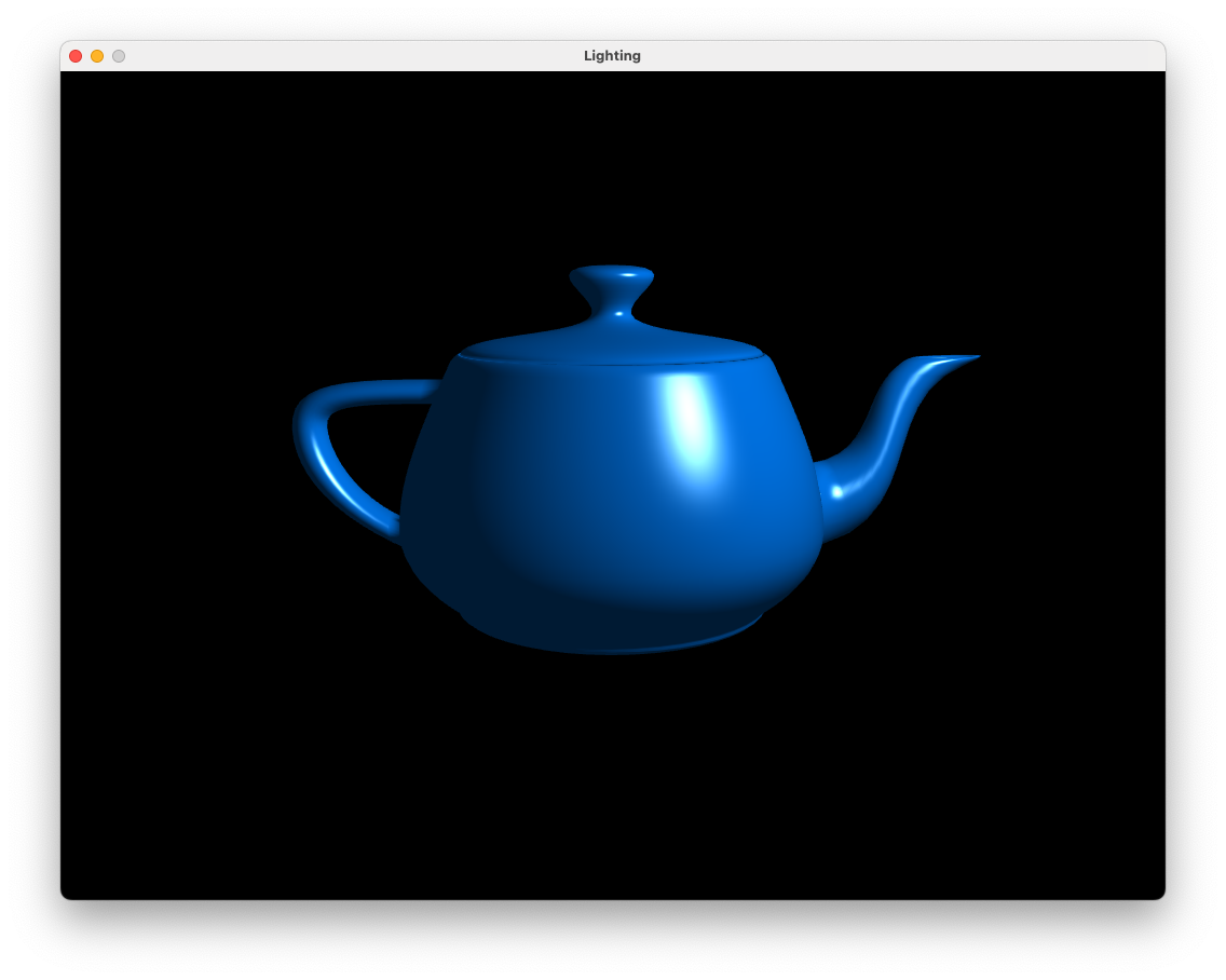
Fig. 8.14 Ambient, diffuse and reflection: \(k_a = 0.2\), \(k_d = 0.7\), \(k_s = 1.0\), \(N_s = 20\).#
Move the camera around the teapot and notice how the specular highlights (the white bits) change due to the position of the camera and the normal vectors of the teapot surface.
8.2.4. Attenuation#
Attenuation is the gradual decrease in light intensity as the distance between the light source and a surface increases. We can use attenuation to model light from low intensity light source, for example, a candle or torch which will only illuminate an area close to the source. Theoretically attenuation should follow the inverse square law where the light intensity is inversely proportional to the square of the distance between the light source and the surface. However, in practice this tends to result in a scene that is too dark so we calculate attenuation using an inverse quadratic function
where \(d\) is the distance between the light source and the fragment and \(constant\), \(linear\) and \(quadratic\) are coefficients that determine how quickly the light intensity decreases. The graph in Fig. 8.15 shows a typical attenuation profile where the light intensity rapidly decreases when the distance is small levelling off as the distance gets larger.

Fig. 8.15 Attenuation can be modelled by an inverse quadratic function.#
To add attenuation to our scene define the attenuation coefficients in the Lab08_Lighting.cpp file where we defined the other lighting properties
float constant  = 1.0f;
float linear    = 0.1f;
float quadratic = 0.02f;
These values depend on the type of light source being modelled, here we have a weak light source to demonstrate the loss of light intensity over space but for stronger light sources you may wish to experiment with these values. Send the attenuation coefficients to the fragment shader using a uniform like we did for the other lighting properties.
glUniform1f (glGetUniformLocation(shaderID, "constant"), constant);
glUniform1f (glGetUniformLocation(shaderID, "linear"), linear);
glUniform1f (glGetUniformLocation(shaderID, "quadratic"), quadratic);
In the fragment shader declare the uniforms for the attenuation coefficients
uniform float constant;
uniform float linear;
uniform float quadratic;
and then in the main() function add the code to calculate and apply attenuation.
// Attenuation
float distance    = length(lightPosition - fragmentPosition);
float attenuation = 1.0 / (constant + linear * distance + quadratic * distance * distance);

// Fragment colour
fragmentColour = (ambient + diffuse + specular) * attenuation;
To demonstrate the affects of applying attenuation we are going to need some more objects that a positioned a different distances from the light source. In your Lab08_Lighting.cpp file before the render loop define arrays for the position vectors and rotation angles for the teapots (taken from the multiple cubes example from Lab06 3D Worlds).
// Teapot positions
glm::vec3 teapotPositions[] = {
    glm::vec3( 0.0f,  0.0f,  0.0f),
    glm::vec3( 2.0f,  5.0f, -10.0f),
    glm::vec3(-3.0f, -2.0f, -3.0f),
    glm::vec3(-4.0f, -2.0f, -8.0f),
    glm::vec3( 2.0f,  2.0f, -6.0f),
    glm::vec3(-4.0f,  3.0f, -8.0f),
    glm::vec3( 0.0f, -2.0f, -5.0f),
    glm::vec3( 4.0f,  2.0f, -4.0f),
    glm::vec3( 2.0f,  0.0f, -2.0f),
    glm::vec3(-1.0f,  1.0f, -2.0f)
};

// Teapot rotation angles
float teapotAngles[10];
for (unsigned int i = 0 ; i < 10 ; i++)
    teapotAngles[i] = Maths::radians(20.0f * i);
Replace the code used to calculate the model, \(MVP\) and \(MV\) matrices as well as drawing the teapot with the following.
// Send the view matrix to the shader
glUniformMatrix4fv(glGetUniformLocation(shaderID, "V"), 1, GL_FALSE, &camera.view[0][0]);

// Loop through objects
for (unsigned int i = 0; i < 10; i++)
{
    // Calculate model matrix
    glm::mat4 translate = Maths::translate(teapotPositions[i]);
    glm::mat4 scale     = Maths::scale(glm::vec3(0.75f));
    glm::mat4 rotate    = Maths::rotate(teapotAngles[i], glm::vec3(1.0f));
    glm::mat4 model     = translate * rotate * scale;

    // Send the MVP and MV matrices to the vertex shader
    glm::mat4 MV  = camera.view * model;
    glm::mat4 MVP = camera.projection * MV;
    glUniformMatrix4fv(glGetUniformLocation(shaderID, "MVP"), 1, GL_FALSE, &MVP[0][0]);
    glUniformMatrix4fv(glGetUniformLocation(shaderID, "MV"), 1, GL_FALSE, &MV[0][0]);

    // Draw the model
    teapot.draw(shaderID);
}
It would also be useful to render the light source. After the for loop to draw the teapots add the following code
// ---------------------------------------------------------------------
// Draw light sources
// Activate light source shader
glUseProgram(lightShaderID);

// Calculate model matrix
glm::mat4 translate = Maths::translate(lightPosition);
glm::mat4 scale     = Maths::scale(glm::vec3(0.1f));
glm::mat4 model     = translate * scale;

// Send the MVP and MV matrices to the vertex shader
glm::mat4 MVP = camera.projection * camera.view * model;
glUniformMatrix4fv(glGetUniformLocation(lightShaderID, "MVP"), 1, GL_FALSE, &MVP[0][0]);

// Send model, view, projection matrices and light colour to light shader
glUniform3fv(glGetUniformLocation(lightShaderID, "lightColour"), 1, &lightColour[0]);

// Draw light source
sphere.draw(lightShaderID);
// ---------------------------------------------------------------------
Moving the camera to a different position allows us to see the affects of attenuation (Fig. 8.16). Note how the teapots further away from the light source are darker as the light intensity has been reduced.
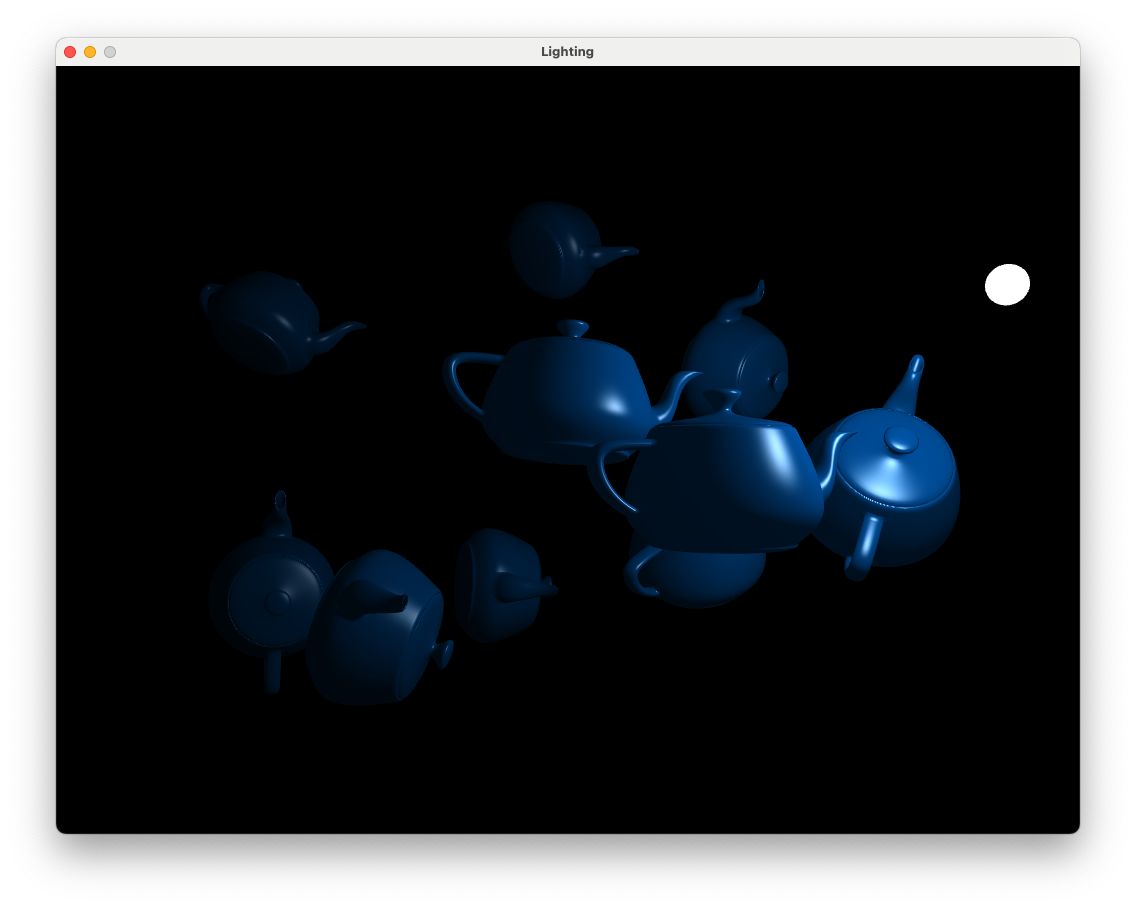
Fig. 8.16 The affects of applying attenuation.#
8.3. Multiple light sources#
To add another light sources to a scene is simply a matter of calculating the ambient, diffuse and specular reflection for the additional light source and then adding them to the fragment colour. We have seen for a single light source we have to define the three light source colours, the position of the light source in the world space and the three attenuation constants. Given that we would like to do this for multiple light sources we need data structure for each light source.
A data structure in C++ and GLSL is defined in a similar way using the struct declaration.
struct Light
{
    vec3 position;
    vec3 colour;
    vec3 direction;
    float constant;
    float linear;
    float quadratic;
    int type;
};
This defines a data structure called Light that contains the information required to calculate the lighting model for a single light source. In the fragment shader we can create a uniform for an array of Light data structures.
uniform int numLights;
uniform Light lightSources[10];
This defines a 10 element array of Light data structures (assuming we have a maximum of 10 light sources) and the actual number of lights sources we have is passed in using the numLights uniform. Then all we need to do is loop through each of the light sources, calculate the fragment colour for the current source and add it to the total fragment colour. Open the file multipleLightsFragmentShader.glsl in the Lab08_Lighting/ folder and you should see the following.
#version 330 core

# define maxLights 10

// Inputs
in vec2 UV;
in vec3 fragmentPosition;
in vec3 Normal;

// Outputs
out vec3 fragmentColour;

// Light struct
struct Light
{
    vec3 position;
    vec3 colour;
    vec3 direction;
    float constant;
    float linear;
    float quadratic;
    int type;
};

// Uniforms
uniform sampler2D diffuseMap;
uniform float ka;
uniform float kd;
uniform float ks;
uniform float Ns;
uniform Light lightSources[maxLights];

// Function prototypes
vec3 pointLight(vec3 lightPosition, vec3 lightColour,
                float constant, float linear, float quadratic);

void main ()
{
    fragmentColour = vec3(0.0, 0.0, 0.0);
    for (int i = 0; i < numLights; i++)
    {
        // Determine light properties for current light source
        vec3 lightPosition  = lightSources[i].position;
        vec3 lightColour    = lightSources[i].colour;
        vec3 lightDirection = lightSources[i].direction;
        float constant      = lightSources[i].constant;
        float linear        = lightSources[i].linear;
        float quadratic     = lightSources[i].quadratic;

        // Calculate point light
        if (lightSources[i].type == 1)
            fragmentColour += pointLight(lightPosition, lightColour,
                                         constant, linear, quadratic);
    }
}

// Calculate point light
vec3 pointLight(vec3 lightPosition, vec3 lightColour,
                float constant, float linear, float quadratic)
{
    // Object colour
    vec3 objectColour = vec3(texture(diffuseMap, UV));

    // Ambient reflection
    vec3 ambient = ka * objectColour;

    // Diffuse reflection
    vec3 light      = normalize(lightPosition - fragmentPosition);
    vec3 normal     = normalize(Normal);
    float cosTheta  = max(dot(normal, light), 0);
    vec3 diffuse    = kd * lightColour * objectColour * cosTheta;

    // Specular reflection
    vec3 reflection = - light + 2 * dot(light, normal) * normal;
    vec3 camera     = normalize(-fragmentPosition);
    float cosAlpha  = max(dot(camera, reflection), 0);
    vec3 specular   = ks * lightColour * pow(cosAlpha, Ns);

    // Attenuation
    float distance    = length(lightPosition - fragmentPosition);
    float attenuation = 1.0 / (constant + linear * distance +
                               quadratic * distance * distance);

    // Fragment colour
    return (ambient + diffuse + specular) * attenuation;
}
Here we have defined a function prototype for the function pointLight() that contains the commands used to calculate the fragment colour for a single point light source. In the main() function we have a for loop to loop through each light source, perform the light calculations for the current light source and add it to the fragment colour.
We also need to make changes to the Lab08_Lighting.cpp file. Add the Light data structure before the main() function declaration
// Light struct
struct Light
{
    glm::vec3 position;
    glm::vec3 colour;
    glm::vec3 direction;
    float constant;
    float linear;
    float quadratic;
    unsigned int type;
};
Since we are using a different file for the fragment shader we need to tell OpenGL to use our new fragment shader which it compiles the shader program.
// Compile shader programs
shaderID      = LoadShaders("vertexShader.glsl", "multipleLightsFragmentShader.glsl");
We now define the lighting properties for multiple lights sources using our Light structure in a C++ vector. Where we defined the colour and position of the single light source, replace the code with the following
// Create vector of light sources
std::vector<Light> lightSources;

// Add first point light source
Light light;
light.position  = glm::vec3(2.0f, 2.0f, 2.0f);
light.colour    = glm::vec3(1.0f, 1.0f, 1.0f);
light.constant  = 1.0f;
light.linear    = 0.1f;
light.quadratic = 0.02f;
light.type      = 1;
lightSources.push_back(light);

// Add second point light source
light.position  = glm::vec3(1.0f, 1.0f, -8.0f);
light.colour    = glm::vec3(1.0f, 1.0f, 1.0f);
light.constant  = 1.0f;
light.linear    = 0.1f;
light.quadratic = 0.02f;
light.type      = 1;
lightSources.push_back(light);
This code creates two light sources, defines the values of the data structures and stores then in the lightSources vector. The lightSources.push_back(light) command adds the current light source to the end of the lightSources vector. Now we need to send the light and material values to the shader using uniforms, comment out the code used to send the light properties to the shader and add the code below.
// Send multiple light source properties to the shader
unsigned int numLights = static_cast<unsigned int>(lightSources.size());
glUniform1i(glGetUniformLocation(shaderID, "numLights"), numLights);
for (unsigned int i = 0; i < numLights; i++)
{
    glm::vec3 viewSpaceLightPosition = glm::vec3(camera.view * glm::vec4(lightSources[i].position, 1.0f));
    std::string idx = std::to_string(i);
    glUniform3fv(glGetUniformLocation(shaderID, ("lightSources[" + idx + "].colour").c_str()), 1, &lightSources[i].colour[0]);
    glUniform3fv(glGetUniformLocation(shaderID, ("lightSources[" + idx + "].position").c_str()), 1, &viewSpaceLightPosition[0]);
    glUniform1f(glGetUniformLocation (shaderID, ("lightSources[" + idx + "].constant").c_str()), lightSources[i].constant);
    glUniform1f(glGetUniformLocation (shaderID, ("lightSources[" + idx + "].linear").c_str()), lightSources[i].linear);
    glUniform1f(glGetUniformLocation (shaderID, ("lightSources[" + idx + "].quadratic").c_str()), lightSources[i].quadratic);
    glUniform1i(glGetUniformLocation (shaderID, ("lightSources[" + idx + "].type").c_str()), lightSources[i].type);
}

// Send object lighting properties to the fragment shader
glUniform1f(glGetUniformLocation(shaderID, "ka"), teapot.ka);
glUniform1f(glGetUniformLocation(shaderID, "kd"), teapot.kd);
glUniform1f(glGetUniformLocation(shaderID, "ks"), teapot.ks);
glUniform1f(glGetUniformLocation(shaderID, "Ns"), teapot.Ns);
Here we simply loop through the vector of light sources and send the values for each individual light to the shader (unfortunately we can’t send a vector of structs using a uniform, we could use GLSL interface blocks but I wanted to keep things simple here).
Finally to draw each light source we loop through each of the light sources and change the translation matrix and light source colour uniform for the current light. Comment out the exist code used to calculate the model matrix and draw the light source and add the following.
for (unsigned int i = 0; i < numLights; i++)
{
    // Calculate model matrix
    glm::mat4 translate = Maths::translate(lightSources[i].position);
    glm::mat4 scale     = Maths::scale(glm::vec3(0.1f));
    glm::mat4 model     = translate * scale;

    // Send the MVP and MV matrices to the vertex shader
    glm::mat4 MVP = camera.projection * camera.view * model;
    glUniformMatrix4fv(glGetUniformLocation(lightShaderID, "MVP"), 1, GL_FALSE, &MVP[0][0]);

    // Send model, view, projection matrices and light colour to light shader
    glUniform3fv(glGetUniformLocation(lightShaderID, "lightColour"), 1, &lightSources[i].colour[0]);

    // Draw light source
    sphere.draw(lightShaderID);
}
Hopefully once you’ve made all of the changes it compiles and runs to show the following
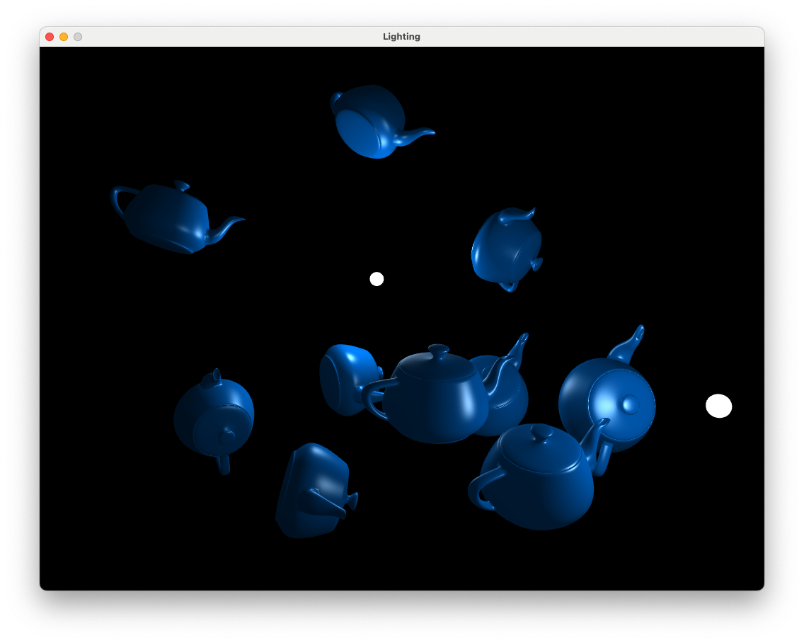
Fig. 8.17 Teapots lit using 2 light sources.#
Use the keyboard and mouse to move the camera around the teapots to see the affects of the light sources.
8.4. Spotlights#
A spotlight is a light source that emits light along a specific direction vector so that only those objects that are within some distance of this vector are illuminated. These are useful for modelling light sources such as flashlights, street lights, car headlights etc.

Fig. 8.18 A spotlight only illuminates fragments where \(\theta < \phi\).#
Consider Fig. 8.18 that shows a spotlight emitting light in the direction given by the \(\mathbf{d}\) vector. The \(\mathbf{L}\) vector points from the light source position to the position of the fragment and the angle \(\phi\) determines the spread of the light. If the angle \(\theta\) between \(\mathbf{L}\) and \(\mathbf{d}\) is less than \(\phi\) then the fragment is illuminated by the spotlight.
To add spotlights to our scene we need to add attributes to the Light data structure for the direction vector \(\mathbf{d}\) and the value of \(\cos(\phi)\) in the fragment shader
vec3 direction;
float cosPhi;
We will be defining a function called spotLight() to calculate our spotlight but first we need to declare the function prototype before the main() function
vec3 spotLight(vec3 lightPosition, vec3 direction, vec3 lightColour,
               float cosPhi, float constant, float linear, float quadratic);
The spotLight() function is below, copy and paste this (or type if out) after the pointLight() function.
// Calculate spotlight
vec3 spotLight(vec3 lightPosition, vec3 lightDirection, vec3 lightColour,
               float cosPhi, float constant, float linear, float quadratic)
{
    // Object colour
    vec3 objectColour = vec3(texture(diffuseMap, UV));

    // Ambient reflection
    vec3 ambient = ka * objectColour;

    // Diffuse reflection
    vec3 light     = normalize(lightPosition - fragmentPosition);
    vec3 normal    = normalize(Normal);
    float cosTheta = max(dot(normal, light), 0);
    vec3 diffuse   = kd * lightColour * objectColour * cosTheta;

    // Specular reflection
    vec3 reflection = - light + 2 * dot(light, normal) * normal;
    vec3 camera     = normalize(-fragmentPosition);
    float cosAlpha  = max(dot(camera, reflection), 0);
    vec3 specular   = ks * lightColour * pow(cosAlpha, Ns);

    // Attenuation
    float distance    = length(lightPosition - fragmentPosition);
    float attenuation = 1.0 / (constant + linear * distance +
                               quadratic * distance * distance);

    // Directional light intensity
    vec3 direction  = normalize(lightDirection);
    cosTheta        = dot(-light, direction);
    float intensity = 0.0;
    if (cosTheta > cosPhi)
        intensity = 1.0;

    // Return fragment colour
    return (ambient + diffuse + specular) * attenuation * intensity;
}
After calculating the ambient, diffuse and specular reflection and attenuation in the same way as for the point light sources we have additional code to calculate \(\cos(\theta)\) between the \(\mathbf{L}\) and \(\mathbf{d}\) vectors. A float intensity is calculated so that its value is 1 if \(\cos(\theta) > \cos(\phi)\) so \(\theta > \phi\) and 0 otherwise. This is then multiplied by the ambient, diffuse and specular reflections so the lighting is turned on or off depending on the position of the fragment.
In the main() function of the fragment shader, add the following to the for loop to calculate the spotlight sources
// Calculate spotlight
if (lightSources[i].type == 2)
    fragmentColour += spotLight(lightPosition, lightDirection, lightColour,
                                cosPhi, constant, linear, quadratic);
So here we are using a type value of 1 to specify a point light source and a value of 2 to specify a spotlight source.
Now we need to define our spotlight source values in the Lab08_Lighting.cpp file which is done in a similar way to the point light sources. Add the direction and cosPhi attributes to the Light data structure.
glm::vec3 direction;
float cosPhi;
and after we defined our point light sources add the following code to add a single spotlight source.
// Add spotlight
light.position  = glm::vec3(0.0f, 3.0f, 0.0f);
light.direction = glm::vec3(0.0f, -1.0f, 0.0f);
light.colour    = glm::vec3(1.0f, 1.0f, 0.0f);
light.constant  = 1.0f;
light.linear    = 0.1f;
light.quadratic = 0.02f;
light.cosPhi    = std::cos(Maths::radians(45.0f));
light.type      = 2;
lightSources.push_back(light);
Here we have defined a single spotlight which is positioned above the first teapot at \((0, 3, 0)\) and with a direction vector pointing straight down so \(\mathbf{d} = (0, -1, 0)\). The colour of the spotlight is yellow since the RGB values are \((1, 1, 0)\) and the spread angle of the light is \(\phi = 45^\circ\). We have also specified that this light source has a type value of 2 for a spotlight. Note that we are only going to use one spotlight for now but have the ability to add more if we want.
We need to send the additional direction and cosPhi values to the shader so where we send the other light properties, add the following code.
glm::vec3 viewSpaceLightDirection = glm::vec3(camera.view * glm::vec4(lightSources[i].direction, 0.0f));
glUniform3fv(glGetUniformLocation(shaderID, ("lightSources[" + idx + "].direction").c_str()), 1, &viewSpaceLightDirection[0]);
glUniform1f(glGetUniformLocation (shaderID, ("lightSources[" + idx + "].cosPhi").c_str()), lightSources[i].cosPhi);
Note that here we calculate the direction vector of the spotlight in the view space by multiplying it by the view matrix. Fingers crossed everything compiles and runs ok and you are presented with the following.
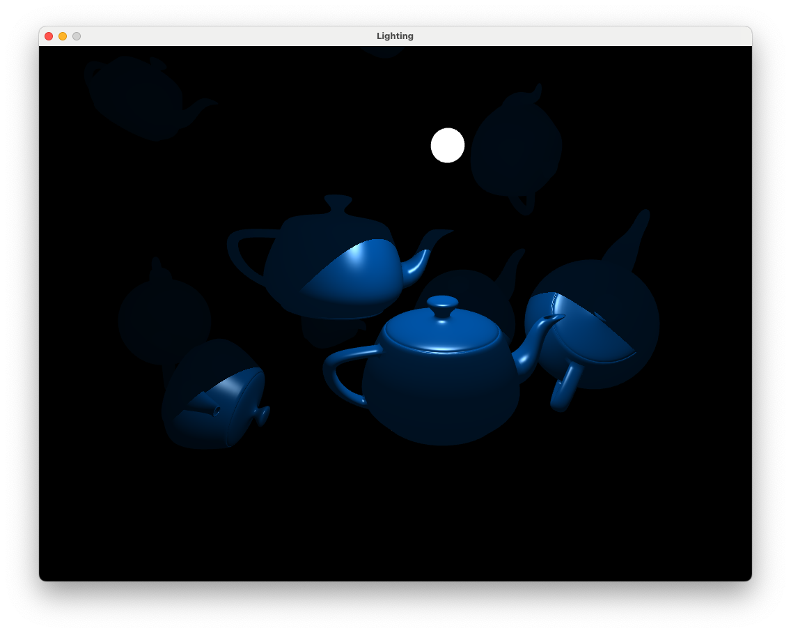
Fig. 8.19 Teapots lit using a spotlight.#
Use the keyboard and mouse to move the camera around the teapots. You may notice that there is an abrupt cutoff between the region illuminated by the spotlight and the region in darkness. In the real world this doesn’t usually happen as light on this edge gets softened by various effects. We can model this softening by dividing the difference between \(\theta\) and \(\phi\) by some small angle \(\delta\) and limiting the values to between 0 and 1. The effect of this can be seen in Fig. 8.20 where the intensity is 1 until \(\phi - \delta\) where it reduces to 0 at \(\phi\). So using this will gradually reduce the intensity are the edge of the illuminated region.

Fig. 8.20 Intensity value over a range of \(\theta\).#
Replace the intensity calculation with the following to soften the edge of the spotlight.
float delta     = radians(2.0);
float intensity = clamp((cosTheta - lightSource.cosPhi) / delta, 0.0, 1.0);
The clamp(x, a, b) limits the value of x so that is is not less than a and not greater than b.
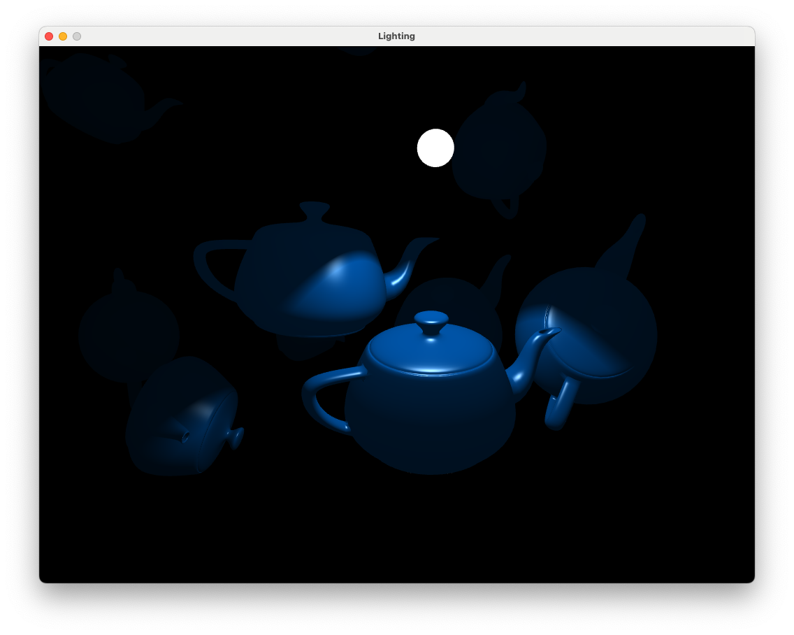
Fig. 8.21 Teapots lit using a spotlight with softened edges.#
8.5. Directional light#
The final light source type we will look at is directional light. When a light source is far away the light rays are very close to being parallel. It does not matter where the object is in the view space as all objects are lit from the same direction.

Fig. 8.22 Directional lighting#
The lighting calculations are the same as for the other light sources seen above with the exception that we do not need the light source position and we do not apply the attenuation. The light vector \(\mathbf{L}\) is simply the direction vector \(\mathbf{d}\) negated.
We are going to use a function to calculate the directional lighting, add the function prototype before the main() function
vec3 directionalLight(vec3 lightDirection, vec3 lightColour);
and then copy and paste (or type out) the following code at the bottom of the file
// Calculate directional light
vec3 directionalLight(vec3 lightDirection, vec3 lightColour)
{
    // Object colour
    vec3 objectColour = vec3(texture(diffuseMap, UV));

    // Ambient reflection
    vec3 ambient = ka * objectColour;

    // Diffuse reflection
    vec3 light     = normalize(-lightDirection);
    vec3 normal    = normalize(Normal);
    float cosTheta = max(dot(normal, light), 0);
    vec3 diffuse   = kd * lightColour * objectColour * cosTheta;

    // Specular reflection
    vec3 reflection = - light + 2 * dot(light, normal) * normal;
    vec3 camera     = normalize(-fragmentPosition);
    float cosAlpha  = max(dot(camera, reflection), 0);
    vec3 specular   = ks * lightColour * pow(cosAlpha, Ns);

    // Return fragment colour
    return ambient + diffuse + specular;
}
Once we’ve defined the function to calculate the directional light we need to tell our main() function to use it and add the directional light colour to the fragment colour. Add the following code to the for loop.
// Calculate directional light
if (lightSources[i].type == 3)
    fragmentColour += directionalLight(lightDirection, lightColour);
Now we need to define a directional light source in the Lab08_Lighting.cpp file.
// Add directional light
light.direction = glm::vec3(1.0f, -1.0f, 0.0f);
light.colour    = glm::vec3(1.0f, 0.0f, 0.0f);
light.type      = 3;
lightSources.push_back(light);
Here we define a directional light source with rays coming down from the top left as we look down the \(z\)-axis. We have also specified that our directional light source is red since the RBG values are \((1, 0, 0)\).
Run your program and you should see something similar to the following
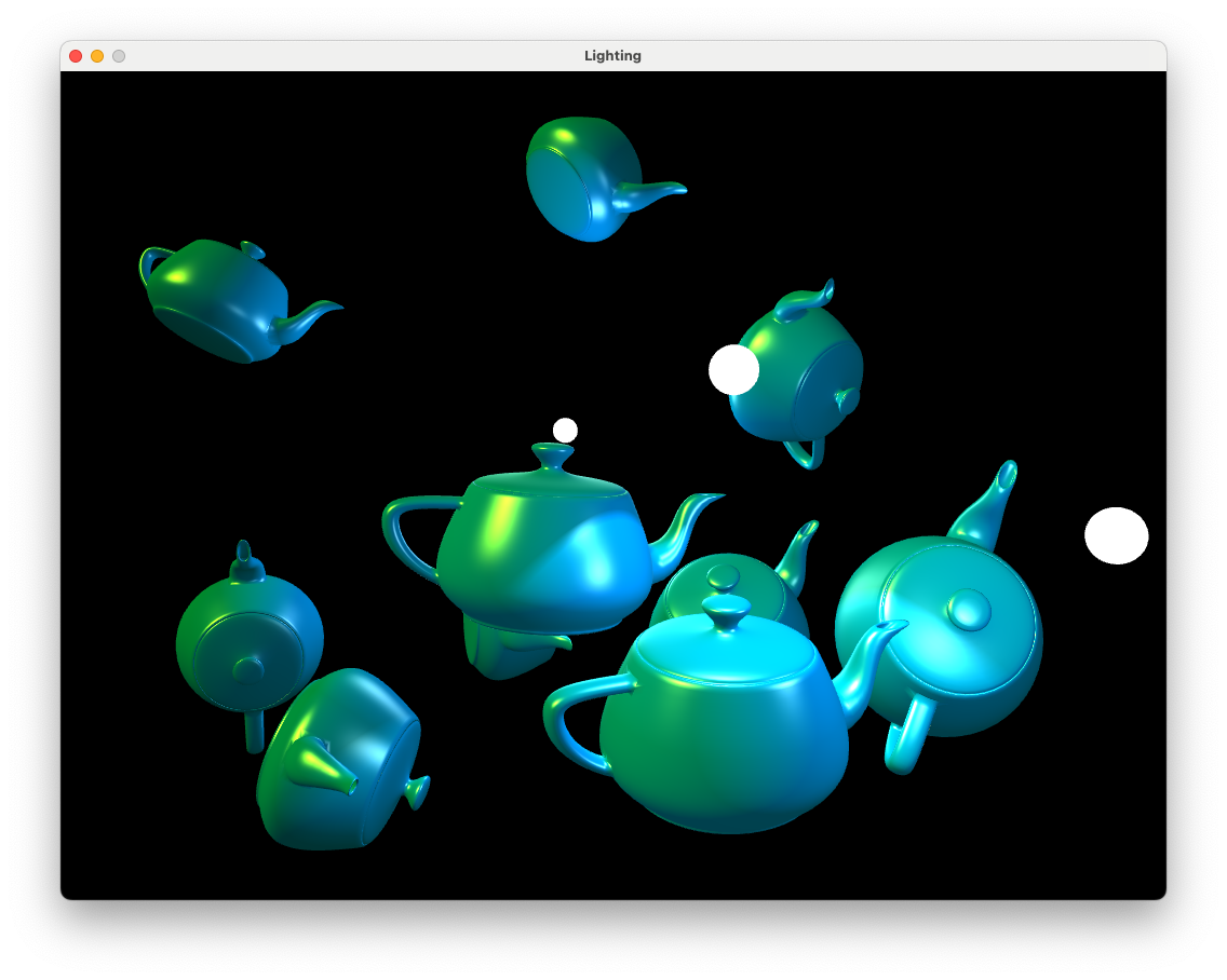
Fig. 8.23 Directional and point light sources.#
We can see that the teapots have been illuminated from a directional light source from the left hand side in addition to the two point light sources and the spotlight.
8.6. Exercises#
Experiment with the positions, colours and material properties of the various light sources to see what effects they have.
Use a spotlight to model a flashlight controlled by the user such that the light is positioned at
camera.position, is pointing in the same direction ascamera.directionand has a spread of \(\phi = 20^\circ\). Turn off all other light sources (either by commenting out code or setting the colours to zero) for extra spookiness.
Change the colour of the second point light source to magenta and rotate its position in a circle centred at (0,0,-5) with radius 5. Turn off any spotlights and directional lighting. Hint: the co-ordinates of points on a circle can be calculated using \((x, y, z) = (0,0,-5) + 5 * (\cos({\tt time}), 0, \sin(\tt time))\).
The planet Narkov has a red sun and a single day lasts for just 5 of our seconds. Use directional lighting to model the illumination of the sun as it passes through the sky and also beneath the horizon (fortunately Narkovians like tea so using our teapots would not seem unusual). The background colour can also be changed to match the colour of the light source.
8.7. Creating an .obj file in Blender#
To create an .obj file we can use the popular open source application Blender (this is installed on the machines in the Dalton building).
Create your object in blender and sort out the material textures, UV co-ordinates etc. (lots of tutorials on youtube to help you with this). Or you can import a model produced by someone else (be sure to give credit if doing this).
Click on File > Export > Wavefront (.obj)
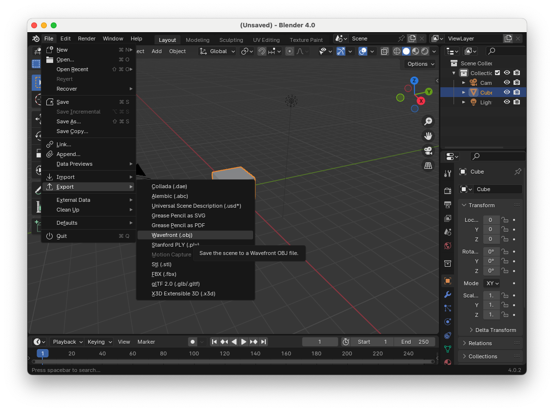
Make sure Include Normals, Include UVs and Triangular Faces are selected.
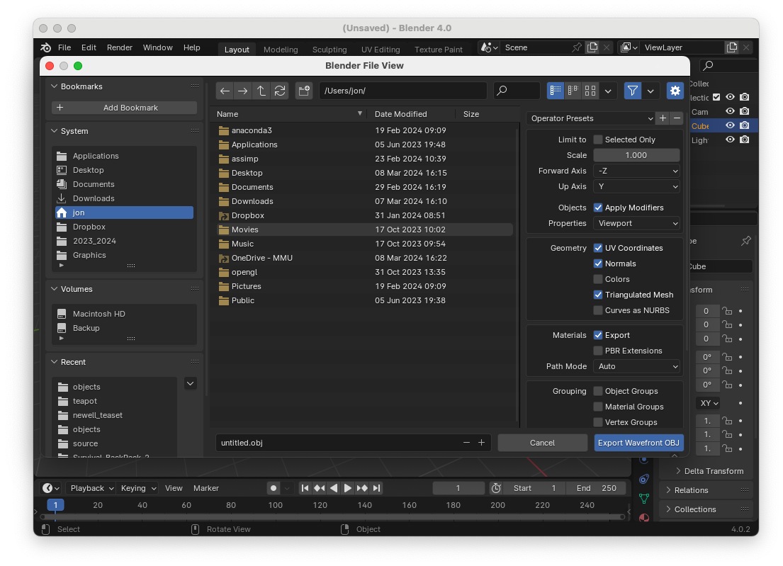
Navigate to your chosen folder e.g.,
Lab10_Lighting/objects/, and give it an appropriate name.
Note
The Model class that we are using here is very simple and will only work with simple models.
8.8. Video walkthrough#
The video below walks you through these lab materials.