2. Basic Shapes in OpenGL#
In this lab we will be creating our first graphics application in OpenGL.
If all has gone to plan you should be looking at a boring window with a grey background shown in Fig. 2.1. Familiarise yourself with the source files. For now, this contains the main C++ program Lab02_Basic_shapes.cpp in the source/ folder, the header file shader.hpp in the headers/ folder and associated code file shader.cpp in the source/ folder.
Fig. 2.1 The “hello window” example (boring isn’t it)#
You can terminate your application by pressing the escape key or simply closing the window.
2.1. Define a triangle#
As you will probably agree, creating a plain grey window isn’t the most interesting of applications. What would make it much more exciting is to draw simple shapes in the window. The simplest shape, and one which we use extensively in computer graphics, is a triangle. We are going to draw the triangle from Fig. 2.2.

Fig. 2.2 The vertices of our triangle.#
OpenGL expects the \(x\), \(y\) and \(z\) co-ordinates of all vertices to be between \(-1\) and \(1\) where the \(x\) and \(y\) axes point to the right and up respectively and the \(z\)-axis points out from the screen. For now we are going to draw a triangle with vertex co-ordinates \((-0.5,-0.5,0)\), \((0.5,-0.5,0)\) and \((0,0.5,0)\) for the bottom-left, bottom-right and top vertices respectively.
The first change we are going to make to our program is to define an array containing the triangle vertices. Enter the following code into the Lab02_Basic_shapes.cpp file after the window has been created.
// Define vertices
const float vertices[] = {
    // x     y     z
    -0.5f, -0.5f, 0.0f,
     0.5f, -0.5f, 0.0f,
     0.0f,  0.5f, 0.0f
};
2.1.1. Vertex Buffer Object (VBO)#
OpenGL uses Buffer Objects (BO) so store data, so to store the vertex co-ordinates of our triangle we need to create a Vertex Buffer Object (VBO) and copy the contents of the vertices array into it. Enter the following after we’ve created the VAO.
// Create Vertex Buffer Object (VBO)
unsigned int VBO;
glGenBuffers(1, &VBO);
glBindBuffer(GL_ARRAY_BUFFER, VBO);
glBufferData(GL_ARRAY_BUFFER, sizeof(vertices), vertices, GL_STATIC_DRAW);
The functions used here are:
glGenBuffers()generates a buffer object with the nameVBOglBindBuffer()binds the VBO toGL_ARRAY_BUFFERwhich tells OpenGL that the VBO contains vertex attributesglBufferData()creates a new data store for the VBO, tells OpenGL where to find the data that is to be stored in the VBO and what it is to be used for (GL_STATIC_DRAWmeans the data is not going to be modified)
2.1.2. Vertex Array Object (VAO)#
In addition to the VBO we also need to create a Vertex Array Object (VAO) which is a container object for the vertex attributes. The VAO does not contain any data, instead it references other buffer objects, e.g., the VBO. To create a VAO enter the following into your Lab02_Basic_shapes.cpp file after the vertices array.
// Create the Vertex Array Object (VAO)
unsigned int VAO;
glGenVertexArrays(1, &VAO);
glBindVertexArray(VAO);
The functions used here are:
glGenVertexArrays()generates a VAO with the nameVAOglBindVertexArray()binds the VAO
2.2. Shaders#
Now we have defined our triangle vertices and created the VAO and VBO we now need to tell OpenGL how to display the triangle. This is done using a shader program that OpenGL uses to tell it how to display each pixel in our window. The shader programs are written in GLSL (OpenGL Shader Language) which is a language similar to C.

A basic shader program consists of two separate programs: a vertex shader and a fragment shader. The vertex shader is called by OpenGL once for each vertex and calculates the position of the current vertex and stores it in a special GLSL vector called gl_Position.
The gl_Position values are passed to the rasteriser which determines the fragments that forms the shape defined by the vertices. The fragment shader is called once for each fragment and is used to determine the colour of the fragment that is sent to the display.
The shaders are compiled by the application at runtime, we need to write the vertex and fragment shaders and tell OpenGL which shaders we want to use.
2.2.1. Vertex shader#
Open the file vertexShader.glsl in the Lab02_Basic_shapes project in the project explorer. At the moment this is a blank file so enter the following program in this.
#version 330 core

layout(location = 0) in vec3 position;

out vec3 Colour;

void main()
{
    // Output vertex position
    gl_Position = vec4(position, 1.0);
}
This is the GLSL program for a simple vertex shader. It takes in a single 3-element vector position that contains the \((x,y,z)\) co-ordinates of a vertex and outputs the 4-element vector gl_Position containing the these co-ordinates. Note that the individual elements of a vector in GLSL can be accessed using vector.x, vector.y and vector.z so we could have used the following instead.
gl_Position = vec4(position.x, position.y, position.z, 1.0)
You may be wondering why gl_Position is a 4-element vector with an additional 1 and not a 3-element vector, don’t worry about this for now it will be explained later on.
2.2.2. Fragment shader#
Open the file fragmentShader.glsl from the project explorer and enter the following program.
#version 330 core

out vec3 colour;

void main()
{
    colour = vec3(1.0f, 0.0f, 0.0f); // RGB
}
This fragment shader outputs a single 3-element vector called colour which defines the colour of the fragment using the RGB colour model. Each colour in the visible spectrum can be defined using a combination of the three primary colours, red, green and blue. The amount of each of the primary colours is given by a value in range 0 to 1. Here we have defined the colour vector using red = 1, blue = 0, green = 0 so our fragment (and all fragments in the triangle) will be rendered in red.
2.2.3. Shader program#
We now need to combine the vertex and fragment shaders into a single shader program. To do this we are going use the function LoadShaders() written by contributors of opengl-tutorial.org. In the Lab02_Basic_shapes.cpp file enter the following after you have created the VBO.
// Compile shader program
unsigned int shaderID;
shaderID = LoadShaders("vertexShader.glsl", "fragmentShader.glsl");
This code creates a program object which will be referred to by the integer shaderID. Now that we have an ID for our shader programmes, we need to instruct OpenGL to use it. To do this enter the following code
// Use the shader program
glUseProgram(shaderID);
2.3. Draw the triangle#
So we have created the VAO and VBO, and written the shaders we can now draw the triangle. The commands used to render a frame are contained in a while loop known as a render loop. This loop will continue until the window is closed or the escape key is pressed.
We need to bind the VBO to the VAO and tell OpenGL where to find this data. To do this add the following code after clearing the window
// Send the VBO to the shaders
glEnableVertexAttribArray(0);
glBindBuffer(GL_ARRAY_BUFFER, VBO);
glVertexAttribPointer(0,         // attribute
                      3,         // size
                      GL_FLOAT,  // type
                      GL_FALSE,  // normalise?
                      0,         // stride
                      (void*)0); // offset
The three functions we’ve used here are:
glEnableVertexAttribArray()enables a generic vertex array so we can pass our triangle data to OpenGLglBindBuffer()binds our VBO to an array bufferglVertexAttribPointer()tells OpenGL how to interpret the data we are sending it
The input arguments for the glVertexAttribPointer() function are explained below
Argument |
Explanation |
|---|---|
Attribute |
A number that defines which vertex attribute we want to configure. In the vertex shader we used |
Size |
How many values does the vertex attribute have. Here we have (x,y,z) co-ordinates so this is 3. |
Type |
Our co-ordinates are floats. |
Normalise |
We have already set out vertex co-ordinates in NDC (i.e., in the range -1 to 1) so we set this to false. |
Stride |
The space between consecutive vertex attributes. Here one vertex immediately follows the next, so this is zero. |
Offset |
Where does the first data point appear in the buffer? For us this is at the beginning, so we set it to 0. |
Now we instruct OpenGL to draw the triangle, add the following code.
// Draw the triangle
glDrawArrays(GL_TRIANGLES, 0, 3);

glDisableVertexAttribArray(0);
The functions used here are:
glDrawArrays()tells OpenGL to draw whatever data is defined in the VAO. The first argumentGL_TRIANGLEStells OpenGL that we want to draw a triangle, the second argument0specifies that the first vertex starts at the 0 index in the buffer and the third argument3specifies that we have 3 vertices.glDisableVertexAttribArray(0)disables the vertex array containing the VBO since it is no longer needed. The input argument0is the attribute number used in theglEnableAttribArray()function.
Don’t get too excited just yet. As good programmers we should clean up after ourselves and not leave bits of data lying around. After the close of the do/while loop we de-allocate the vertex and buffer objects as well as deleting the shader program.
// Cleanup
glDeleteBuffers(1, &VBO);
glDeleteVertexArrays(1, &VAO);
glDeleteProgram(shaderID);
Compile and run your program. After all the syntax errors and bugs have been resolved (unless you are very lucky there will be at least one) you should be presented with a window within which is your red triangle that you have created.
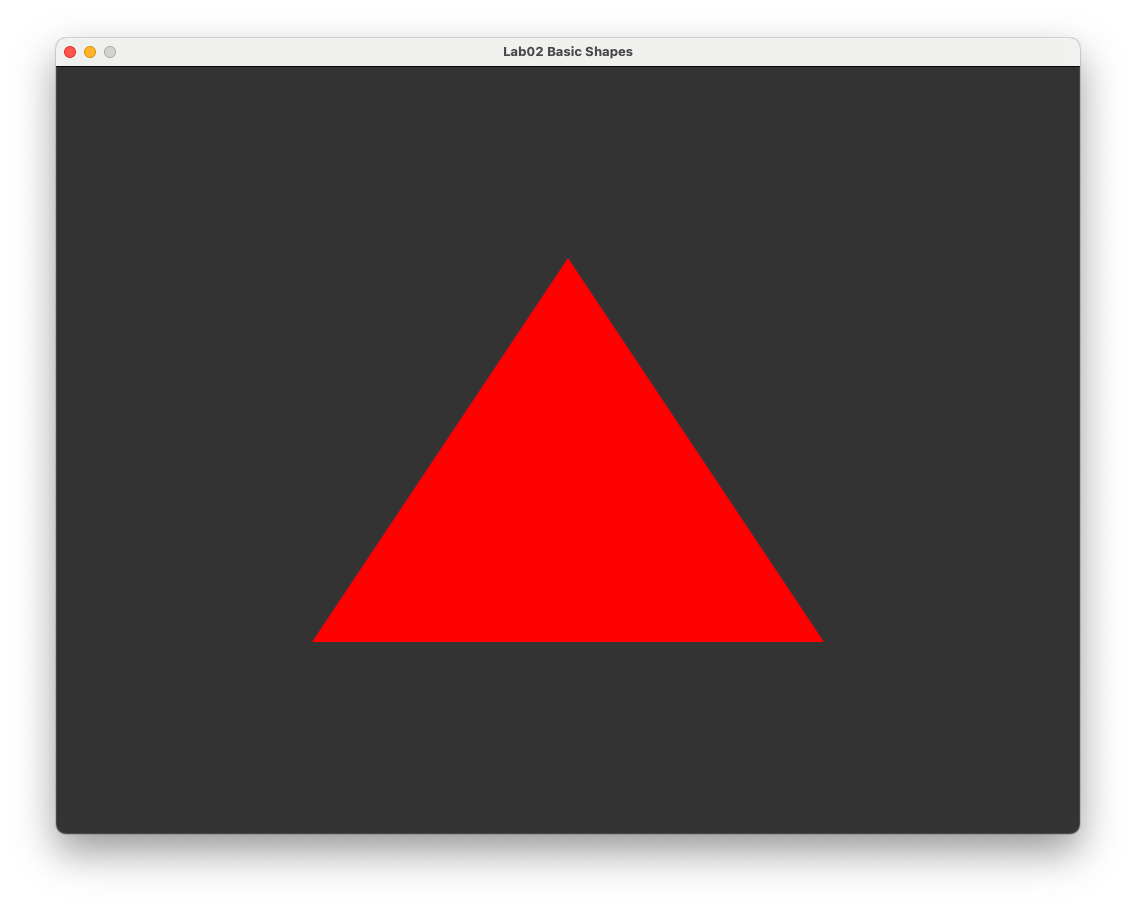
Fig. 2.3 The “hello triangle” example#
2.4. More colours#
After basking in the glory of your achievements for a few minutes the initial excitement may begin to wane, and your natural curiosity will cause you to wonder whether we can use more than one colour. Well of course, all we need to do is tell OpenGL what colours we want to use for each vertex.
Create an array that contains RGB colour data for each vertex by entering the following code after we created the vertices array.
// Define vertex colours
const float colours[] = {
    // R   G     B
    1.0f, 0.0f, 0.0f,
    0.0f, 1.0f, 0.0f,
    0.0f, 0.0f, 1.0f
};
Here we have assigned the colour red to the first (bottom-left) vertex, green to the second (bottom-right) vertex and blue to the third (top) vertex. Like we did with the vertex buffer, we need to create and bind a buffer for the colours.
// Create colour buffer
unsigned int colourBuffer;
glGenBuffers(1, &colourBuffer);
glBindBuffer(GL_ARRAY_BUFFER, colourBuffer);
glBufferData(GL_ARRAY_BUFFER, sizeof(colours), colours, GL_STATIC_DRAW);
And where we draw the triangle, we also need to bind the colour buffer to the VAO so it can be sent to the shaders.
// Send the colour buffer to the shaders
glEnableVertexAttribArray(1);
glBindBuffer(GL_ARRAY_BUFFER, colourBuffer);
glVertexAttribPointer(1, 3, GL_FLOAT, GL_FALSE, 0, (void*)0);
You will notice that this code is very similar to the code used to send the VBO to the shader. Here we have use the attribute 1 for the colour buffer, if we had used 0 this would have overwritten the VBO.
If you were to compile and run your program, you might be a little disappointed as your triangle is still red. Well of course, we haven’t told our shaders how to handle colours! Since our colours are associated with the vertices we need to modify the vertex shader to include the colours.
#version 330 core

layout(location = 0) in vec3 position;
layout(location = 1) in vec3 colour;

out vec3 fragmentColour;

void main()
{
    // Output vertex position
    gl_Position = vec4(position.x, position.y, position.z, 1.0);

    // Output vertex colour
    fragmentColour = colour;
}
Here our vertex shader is a little more sophisticated than before. We’ve added another attribute with location = 1 (the same attribute number used in the glVertexAttribPointer() function) for the colour data which is a 3-element vector. Also, since we need to pass the colour data to the fragment shader we need to output it from the vertex shader. We don’t need to do this for he vertex data as gl_Position is outputted automatically.
We also need to modify the fragment shader to take in the fragment colour calculated by the rasteriser and output it to the display.
#version 330 core

in vec3 fragmentColour;

out vec3 colour;

void main()
{
    colour = fragmentColour;
}
Compile and run your program and if everything has gone to plan you should be presented with your new triangle in all its colourful snazzy goodness. Notice how the pixels in between the three vertex pixels have been shaded a colour which are combinations of the three vertex colours red, green and blue. OpenGL has interpolated the colours across the triangle.
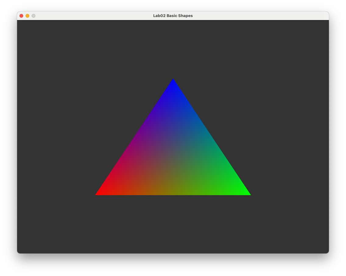
Fig. 2.4 Our snazzy triangle.#
2.5. Adding another triangle#
What could be better than one triangle? Well two triangles of course. Fortunately since we have done all of the grunt work in setting up the buffers for a single triangle adding another is a simple matter of defining the vertex co-ordinates and vertex colours for the additional triangle. Modify the vertices and colours arrays to the following.
// Define vertices
static const float vertices[] = {
    -0.9f, -0.5f, 0.0f,   // triangle 1
    -0.1f, -0.5f, 0.0f,
    -0.5f,  0.5f, 0.0f,
     0.1f, -0.5f, 0.0f,   // triangle 2
     0.9f, -0.5f, 0.0f,
     0.5f,  0.5f, 0.0f
};

// Define vertex colours
static const float colours[] = {
    1.0f, 0.0f, 0.0f,    // triangle 1 (red)
    1.0f, 0.0f, 0.0f,
    1.0f, 0.0f, 0.0f,
    0.0f, 0.0f, 1.0f,    // triangle 2 (blue)
    0.0f, 0.0f, 1.0f,
    0.0f, 0.0f, 1.0f,
};
Here the vertices array now defines six vertices for two triangles placed side-by-side. The colours array defines the first three vertices red and the second three set of vertices blue.
We also need to instruct OpenGL to draw two triangles instead of one. To do this we change the number of vertices we want to draw from 3 to the number of vertices we have. Since each vertex has 3 co-ordinates \((x, y, z)\) and each co-ordinate is a single float then we can calculate the number of vertices we have by dividing sizeof(vertices) by 3 * sizeof(float).
// Draw the triangles
glDrawArrays(GL_TRIANGLES, 0, sizeof(vertices) / (3 * sizeof(float)));
Compiling and running the executable results in the following.
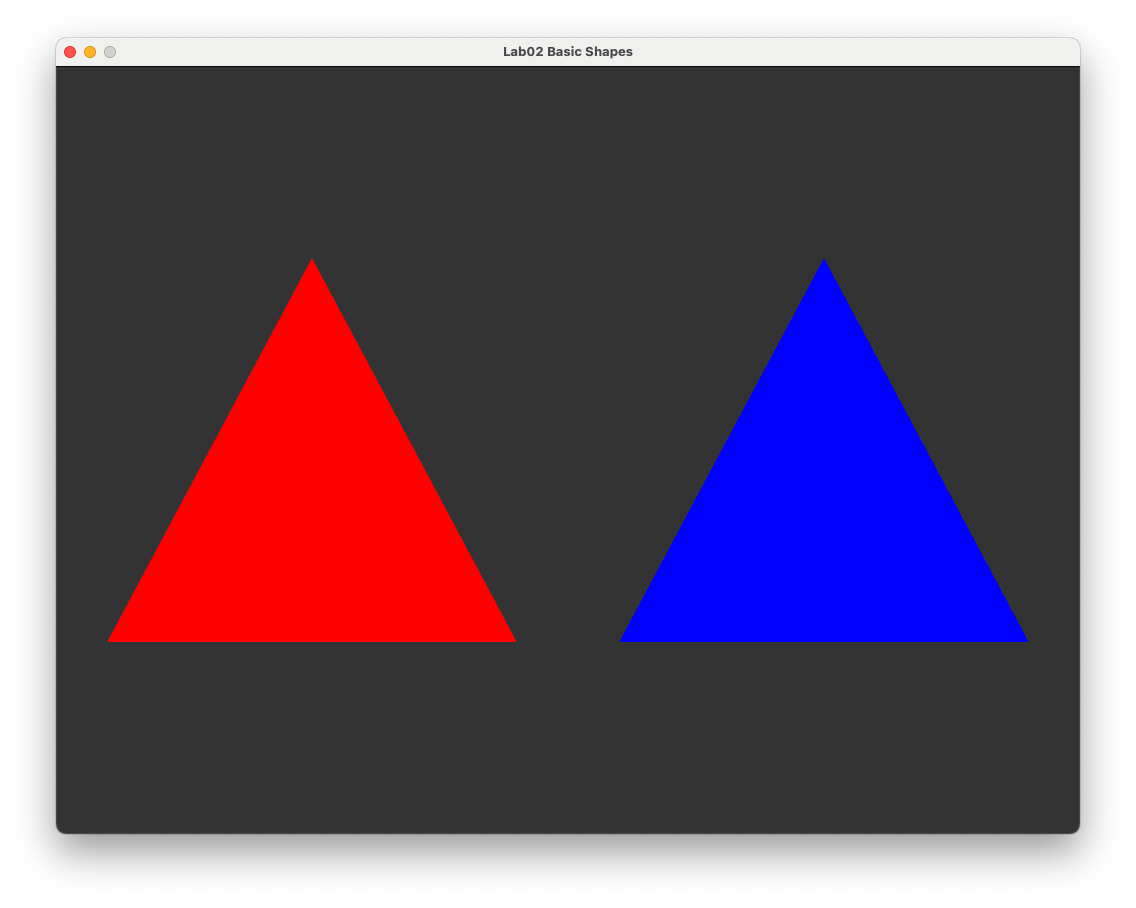
Fig. 2.5 Two triangles#
2.6. Exercises#
Now that you’ve got to the stage where you can draw triangles to the screen and alter the colours lets see if you can do the following.
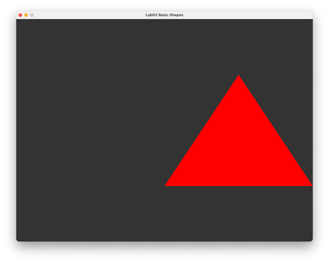
Draw the original triangle but alter the vertex shader to achieve the following results:
(a) the triangle is shifted by 0.5 to the right;
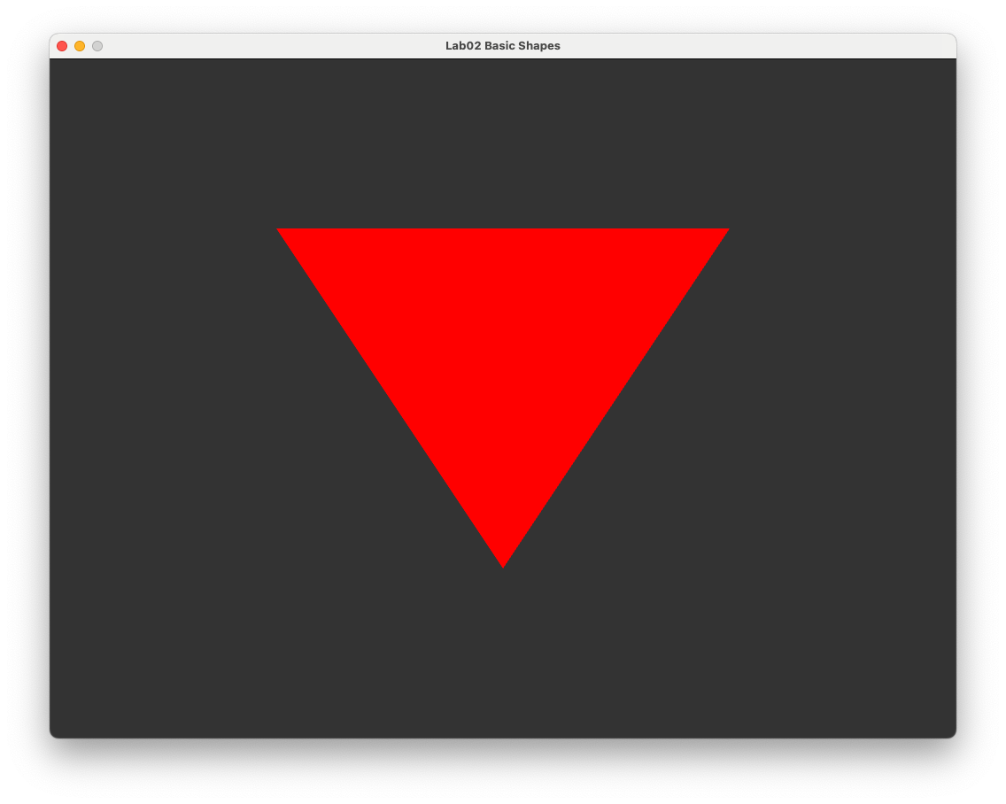
(b) the triangle is drawn upside-down;
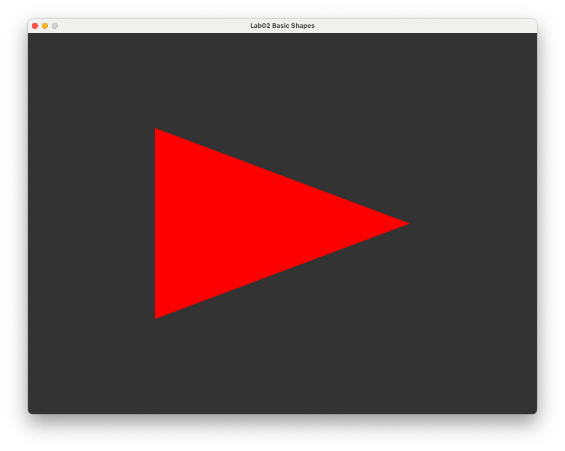
(c) the triangle \(x\) and \(y\) co-ordinates are swapped.
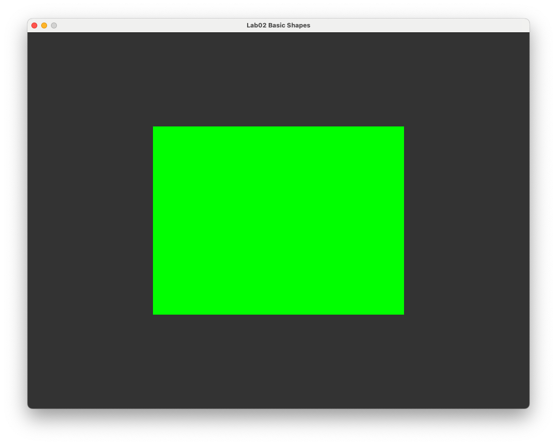
Use two triangles to draw a green rectangle where the lower-left corner has co-ordinates \((-0.5, -0.5, 0.0)\) and the upper-right corner has co-ordinates \((0.5, 0.5, 0.0)\).
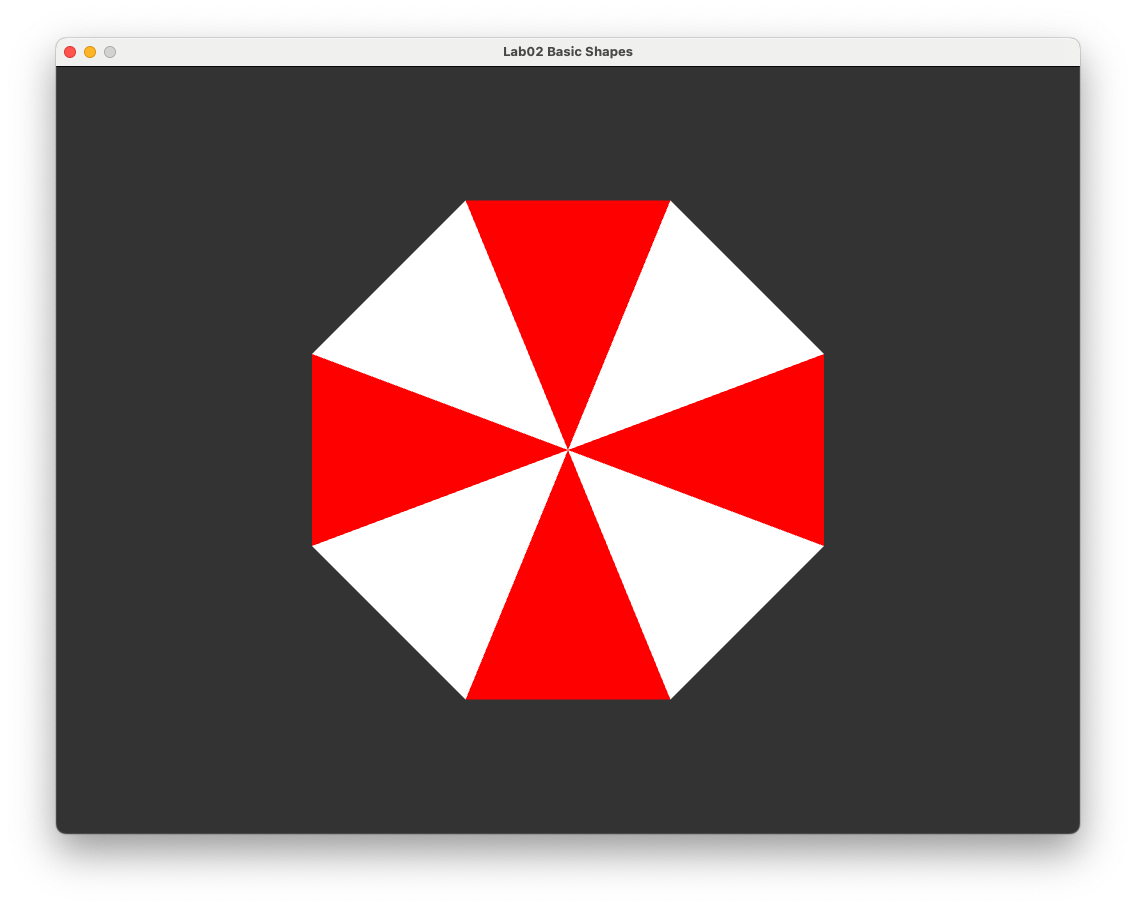
Draw the Umbrella Corporation logo using 8 triangles.