3. Textures#
Texture mapping is a technique for applying a 2D image known as a texture onto a 3D surface. Applying a texture adds detail and complexity to the appearance of 3D objects without the need for modelling intricate geometry.

Fig. 3.1 Mapping a texture to a polygon.#
The texture is a 2D image where each pixel within the texture, known as a textel, is referenced using the texture coordinates given as \((u,v)\) where \(u\) and \(v\) are in the range 0 to 1, i.e., \((0,0)\) corresponds to the textel in the bottom-left corner and \((1,1)\) corresponds to the textel in the top-right corner. When a fragment is created by the shader the corresponding texture co-ordinates are calculated and the sample colour of the textel is used for the fragment. Fortunately we do not need to write a texture mapper functions since these are in OpenGL.
3.1. Texture triangle#
Compile and run the Lab03_Textures project and you should be presented with the image of the red triangle from 2. Basic Shapes in OpenGL shown in Fig. 3.2
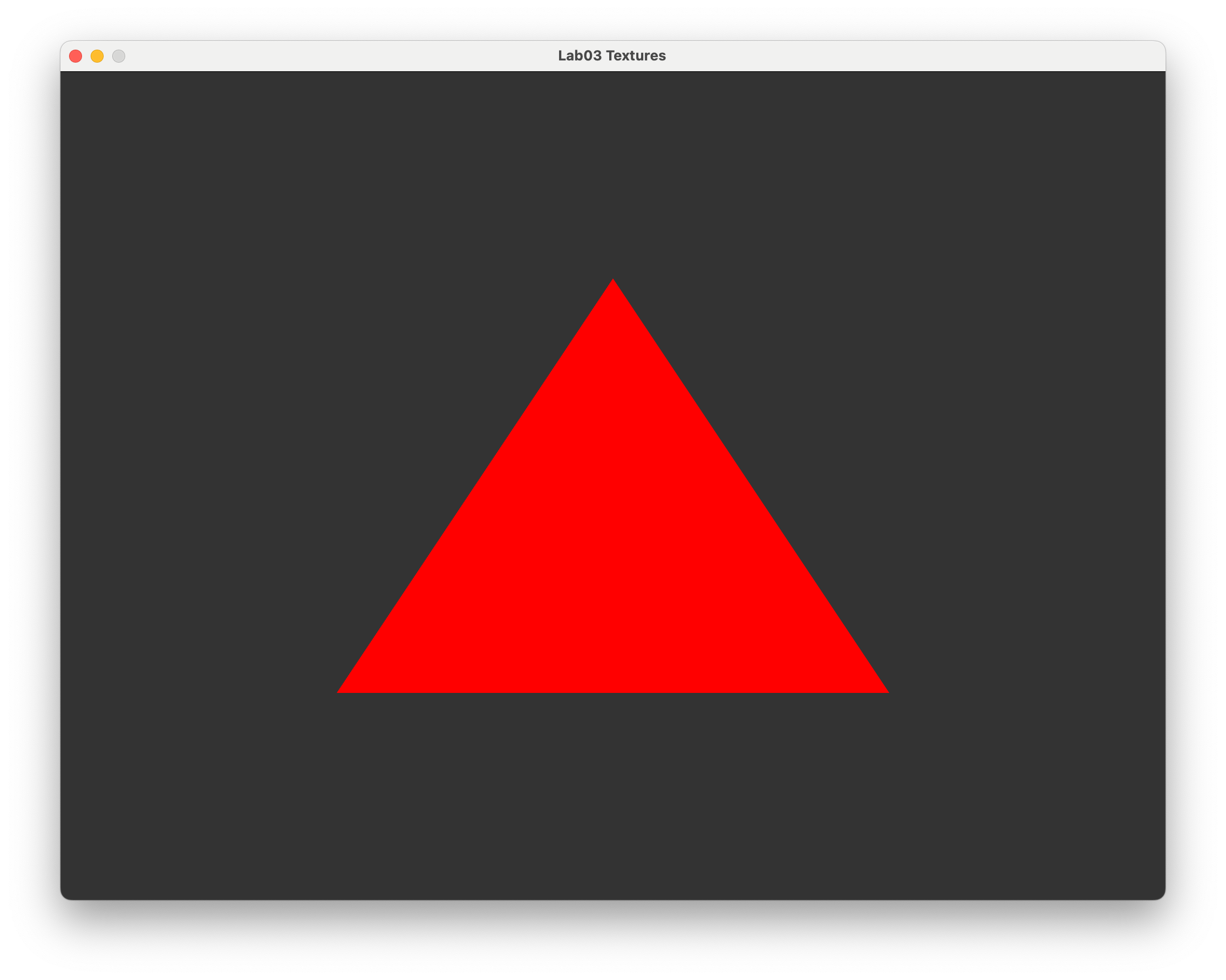
Fig. 3.2 The red triangle from 2. Basic Shapes in OpenGL.#
We will apply a texture to this triangle.
3.1.1. Creating a texture#
The first thing we need to do is create a texture object and bind it to a target so we can call upon it later. Enter the following code to the Lab03_Textures.cpp file after we tell OpenGL to compile the shader program
// Create and bind texture
unsigned int texture;
glGenTextures(1, &texture);
glBindTexture(GL_TEXTURE_2D, texture);
Here we have defined a target called texture which is an integer used to refer to the texture. The texture is then generated and bound to this target using the glGenTextures() and glBindTexture() functions.
We now need to load a image into our texture. To do this we are going to make use of the stb_image library, the header file for which can be found in the common/ folder. Enter the following code into your program.
// Load texture image from file
const char *path = "../assets/crate.jpeg";
int width, height, nChannels;
stbi_set_flip_vertically_on_load(true);
unsigned char *data = stbi_load(path, &width, &height, &nChannels, 0);
The functions used here are:
stbi_set_flip_vertically_on_load()flips the image vertically since the \((0,0)\) co-ordinate on an images is the top-left corner and OpenGL expects it to be the bottom-right cornerstbi_load()loads the image specified in thepathstring into thedatavariable and the stores the width, height and number of colour channels into the appropriate variables
The texture we are using here is crate.jpeg which is stored in the assets/ folder and represents a side of a wooden crate.
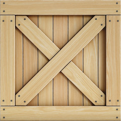
Fig. 3.3 The crate texture.#
After getting the texture data from the image file we tell OpenGL we that have a texture. Enter the following code into your program.
// Specify 2D texture
glTexImage2D(GL_TEXTURE_2D, 0, GL_RGB, width, height, 0, GL_RGB,
                GL_UNSIGNED_BYTE, data);
glGenerateMipmap(GL_TEXTURE_2D);
The glTexImage2D() function tells OpenGL we have a 2D texture which is contained in data. GL_RGB is the format that specifies the number of colours in the texture. Here we are using a JPEG file so the colour each textel is represented by the RGB model. The glGenerateMipmap generates mipmaps for the texture (mipmaps are explained below).
Now that the texture data has been copied to the GPU we can free up memory by adding the following to the program.
// Free the image from the memory
stbi_image_free(data);
3.1.2. Texture co-ordinates#
So we have created a texture and told OpenGL all about it. Now we need specify how we want to use the texture. To do this for each of the vertices of the triangle we need to define the corresponding \((u, v)\) texture co-ordinates. This is done in a the same way as the triangle vertices, i.e., define an array containing the co-ordinates, create a buffer and copy the co-ordinates to this buffer.
Enter the following code after we defined the vertices array (you may need to scroll up a bit).
// Define texture coordinates
const float uv[] = {
    // u   v
    0.0f, 0.0f,
    1.0f, 0.0f,
    0.5f, 1.0f
};
Here we have defined an array of float values called uv and specified the texture co-ordinates so that the bottom-left triangle vertex is mapped to the texture co-ordinate \((0, 0)\) at the bottom-left corner of the texture, the bottom-right vertex is mapped to \((1,0)\) at the bottom-right corner of the texture and the top vertex is mapped to \((0.5, 1)\) in the middle of the top edge of the texture.
The buffer for the texture co-ordinates is created in the same was as for the triangle vertices. Enter the following code after the VBO was created.
// Create texture buffer
unsigned int uvBuffer;
glGenBuffers(1, &uvBuffer);
glBindBuffer(GL_ARRAY_BUFFER, uvBuffer);
glBufferData(GL_ARRAY_BUFFER, sizeof(uv), uv, GL_STATIC_DRAW);
Sending the texture co-ordinates to the GPU is done in the same way as for the VBO. Enter the following code after we send the VBO to the GPU (this is in the render loop so scroll down a bit).
// Send the UV buffer to the shaders
glEnableVertexAttribArray(1);
glBindBuffer(GL_ARRAY_BUFFER, uvBuffer);
glVertexAttribPointer(1, 2, GL_FLOAT, GL_FALSE, 0, (void*)0);
Note that since each texture co-ordinates requires just 2 floats for \((u,v)\) instead of 3 for the vertex co-ordinates \((x,y,z)\) the second argument in the glVertexAttribPointer() function is 2 instead of 3.
3.1.3. Shaders#
3.1.3.1. Vertex shader#
Recall that the vertex shader deals with the vertex co-ordinates and is used by OpenGL to calculate the co-ordinates of the fragment. So in addition to passing the \((x, y, z)\) co-ordinates of the vertices we must also pass the \((u, v)\) co-ordinates of the textels that correspond to the triangle vertices.
Edit the vertexShader.glsl file in the Lab03_Textures project so that it looks like the following.
#version 330 core

// Inputs
layout(location = 0) in vec3 position;
layout(location = 1) in vec2 uv;

// Outputs
out vec2 UV;

void main()
{
    // Output vertex position
    gl_Position = vec4(position, 1.0);

    // Output texture co-ordinates
    UV = uv;
}
You may notice some changes from our vertex shader from Lab02 Basic Shapes in OpenGL. We now have a second input uv which is a 2-element vector which are the \((u,v)\) texture coordinates which are outputted as the 2-element vector UV (remember that the gl_Position vector is passed to the fragment shader by default).
3.1.3.2. Fragment shader#
The fragment shader is where we need to retrieve the sample colour from the texture. Edit the fragmentShader.glsl file so that it looks like the following.
#version 330 core

// Input
in vec2 UV;

// Output
out vec3 colour;

// Uniforms
uniform sampler2D texture;

void main()
{
    colour = vec3(texture(texture, UV));
}
Here we now have an input of the 2-element vector uv which has been outputted from the vertex shader. Since our texture is a 2D image then we use the sampler2D GLSL type to declare the uniform textureMap (uniforms are explained below). The colour of the fragment is taken from the texture using the texture() function where the first argument is the name of the texture uniform and the second argument is the \((u,v)\) texture co-ordinates of the fragment.
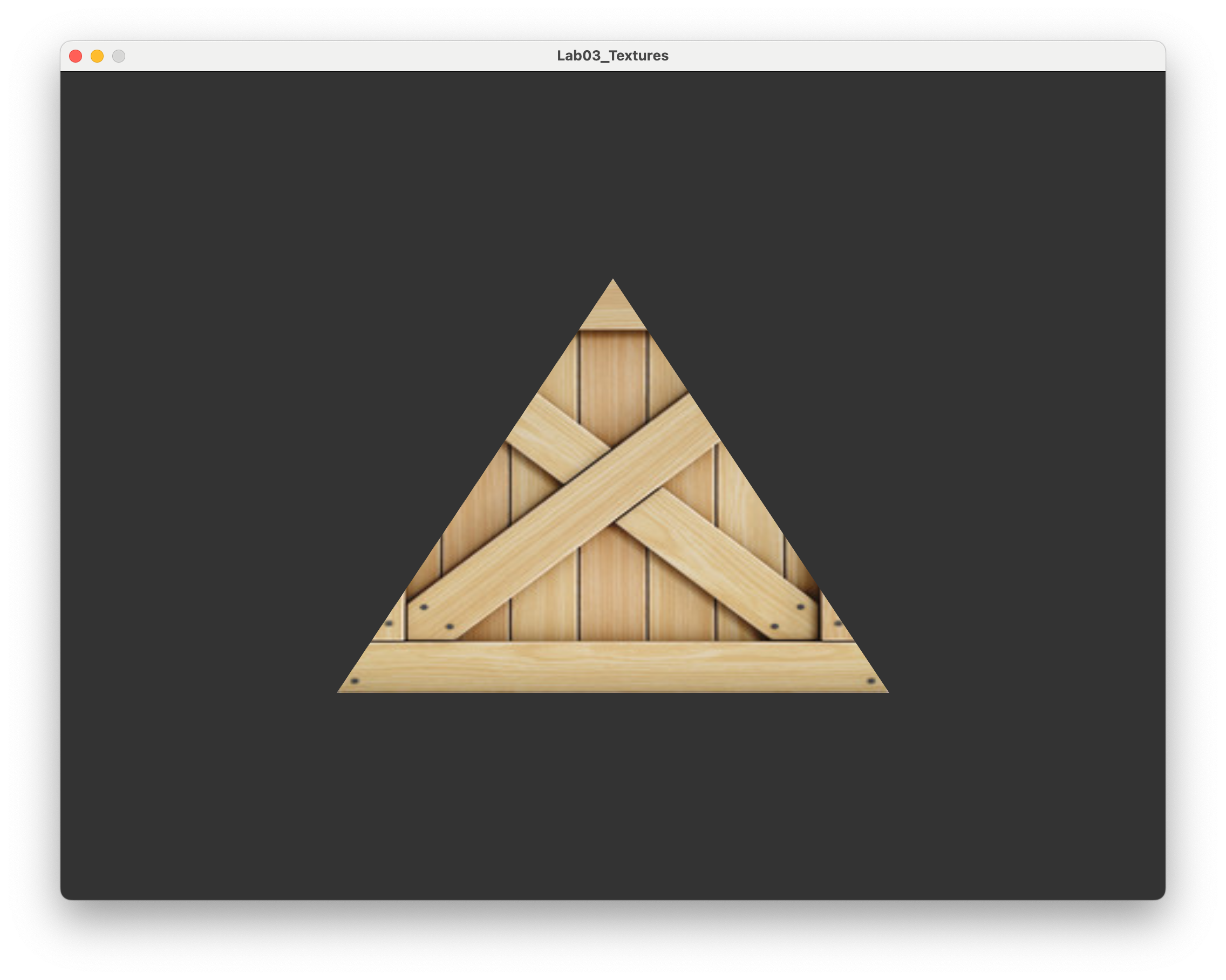
Compile and run program and, after sending a prayer to the programming gods, you should be presented with your triangle which has now been textured using the crate texture.
3.2. Texture rectangle#
Our texture triangle is great and all but doesn’t really look like a realistic object. Since the original texture is rectangular, lets create a rectangle out of two triangles with the appropriate texture mapping.

Fig. 3.4 A rectangle constructed using two triangles.#
So the lower-right (blue) triangle has vertex co-ordinates \((-0.5, -0.5, 0)\), \((0.5, -0.5, 0)\) and \((0.5, 0.5, 0)\) and the upper-left (red) triangle has vertex co-ordinates \((-0.5, -0.5, 0)\), \((0.5, 0.5, 0)\) and \((-0.5, 0.5, 0)\). Change the vertices and uv arrays to the following.
// Define vertex positions
static const float vertices[] = {
    -0.5f, -0.5f, 0.0f,    // triangle 1
     0.5f, -0.5f, 0.0f,
     0.5f,  0.5f, 0.0f,
    -0.5f, -0.5f, 0.0f,    // triangle 2
     0.5f,  0.5f, 0.0f,
    -0.5f,  0.5f, 0.0f
};

// Define texture co-ordinates
static const float uv[] = {
    // u    v
    0.0f,  0.0f,    // triangle 1
    1.0f,  0.0f,
    1.0f,  1.0f,
    0.0f,  0.0f,    // triangle 2
    1.0f,  1.0f,
    0.0f,  1.0f
};
Compile and run the program and you should be presented with the more realistic image in Fig. 3.5.
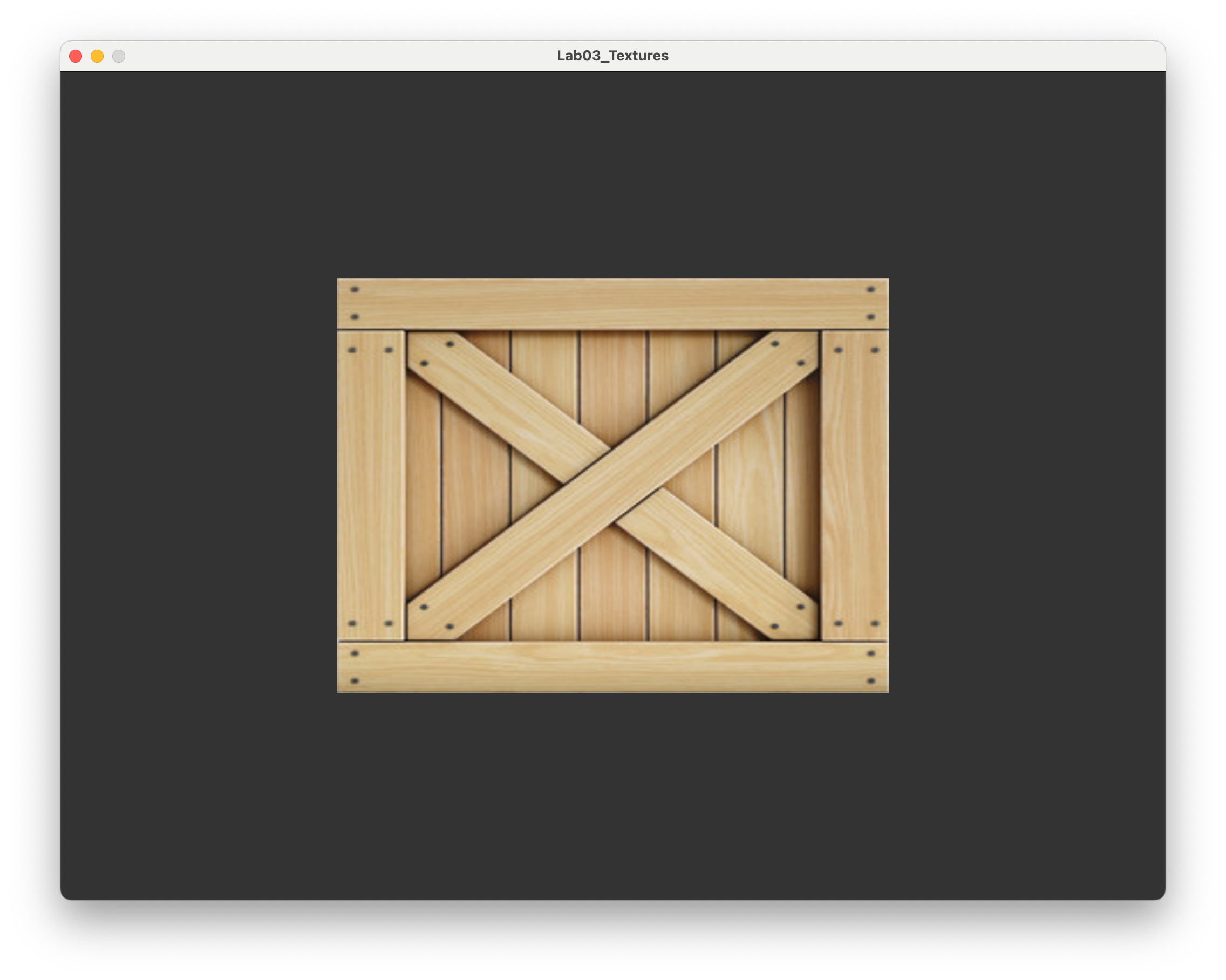
Fig. 3.5 Texture mapped onto two triangles that form a rectangle.#
3.2.1. Element Buffer Objects (EBO)#
Our rectangle is defined using 6 sets of \((x,y,z)\) co-ordinates for the 2 triangles but a rectangle only has 4 vertices. This means we are using 2 extra co-ordinates than we really need to as both of the triangles share the vertices at \((-0.5, -0.5, 0)\) and \((0.5, 0.5, 0)\). This isn’t too bad for our simple rectangle example but for more sophisticated scenes that use thousands of triangles it can be inefficient.
To improve on this we can use an Element Buffer Object (EBO) that contains indices that map a vertex of the rectangle to the vertices array. Consider Fig. 3.6 that shows a rectangle drawn using two triangles. The lower-right triangle is formed using the vertices with indices 0, 1 and 2 and the upper-left triangle is formed using vertices with indices 0, 2 and 3.

Fig. 3.6 The mapping of indices to the rectangle vertices.#
Comment out the code used to define the vertices and uv arrays and enter the following code.
// Define vertex positions
static const float vertices[] = {
    // x     y     z      index
    -0.5f, -0.5f, 0.0f,  // 0       3 -- 2
     0.5f, -0.5f, 0.0f,  // 1       |  / |
     0.5f,  0.5f, 0.0f,  // 2       | /  |
    -0.5f,  0.5f, 0.0f   // 3       0 -- 1
};

// Define texture co-ordinates
static const float uv[] = {
    // u    v      index
    0.0f,  0.0f,  // 0
    1.0f,  0.0f,  // 1
    1.0f,  1.0f,  // 2
    0.0f,  1.0f,  // 3
};

// Define indices
static const unsigned int indices[] = {
    0, 1, 2,  // lower-right triangle
    0, 2, 3   // upper-left triangle
};
As with the other buffer objects we need to create a buffer for the indices, bind it and copy the data across. Enter the following code after we’ve created the texture buffer.
// Create Element Buffer Object (EBO)
unsigned int EBO;
glGenBuffers(1, &EBO);
glBindBuffer(GL_ELEMENT_ARRAY_BUFFER, EBO);
glBufferData(GL_ELEMENT_ARRAY_BUFFER, sizeof(indices), indices,
                GL_STATIC_DRAW);
This is similar to the code used to create the other buffer objects with the exception we are creating an GL_ELEMENT_ARRAY_BUFFER instead of an GL_ARRAY_BUFFER. The last change we need to make in order to use our EBO is to change the function used to draw the triangles from glDrawArrays() to glDrawElements()
// Draw the triangle
glDrawElements(GL_TRIANGLES, sizeof(indices) / sizeof(unsigned int),
                GL_UNSIGNED_INT, 0);
Make this change, compile and run the program and you should see the window from Fig. 3.5. You may be thinking you’ve gone to all of that trouble only for the rectangle to look exactly the same. Well, now we are using fewer floats in the vertices array and we can now use EBOs to draw more sophisticated shapes and 3D models.
3.3. Texture wrapping and filtering#
3.3.1. Texture wrapping#
In our examples above, all of the texture co-ordinates have been in the range from 0 to 1. What happens if we use textures co-ordinates outside of this range? To test this we are going to change our texture to something less symmetrical (you will see why in a minute). Change the path variable to the following
// Load texture image from file
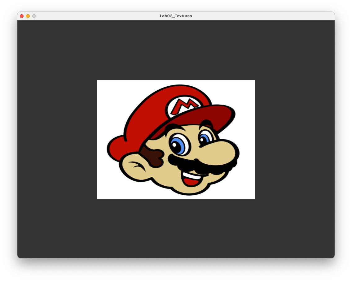
const char *path = "../assets/mario.png";
PNG (Portable Network Graphics) files use the RGBA colour model which is the standard RGB model with an addition Alpha value that determines the opacity of the colours. We need to let OpenGL know that our texture is defined using RGBA so change instances GL_RGB in the glTexImage2D() function to GL_RGBA, i.e.,
// Specify 2D texture
glTexImage2D(GL_TEXTURE_2D, 0, GL_RGBA, width, height, 0, GL_RGBA,
GL_UNSIGNED_BYTE, data);
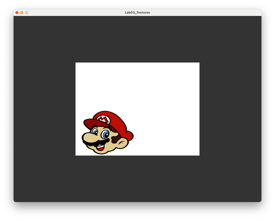
Compile and run the program and you should be presented with a (hopefully) familiar face.
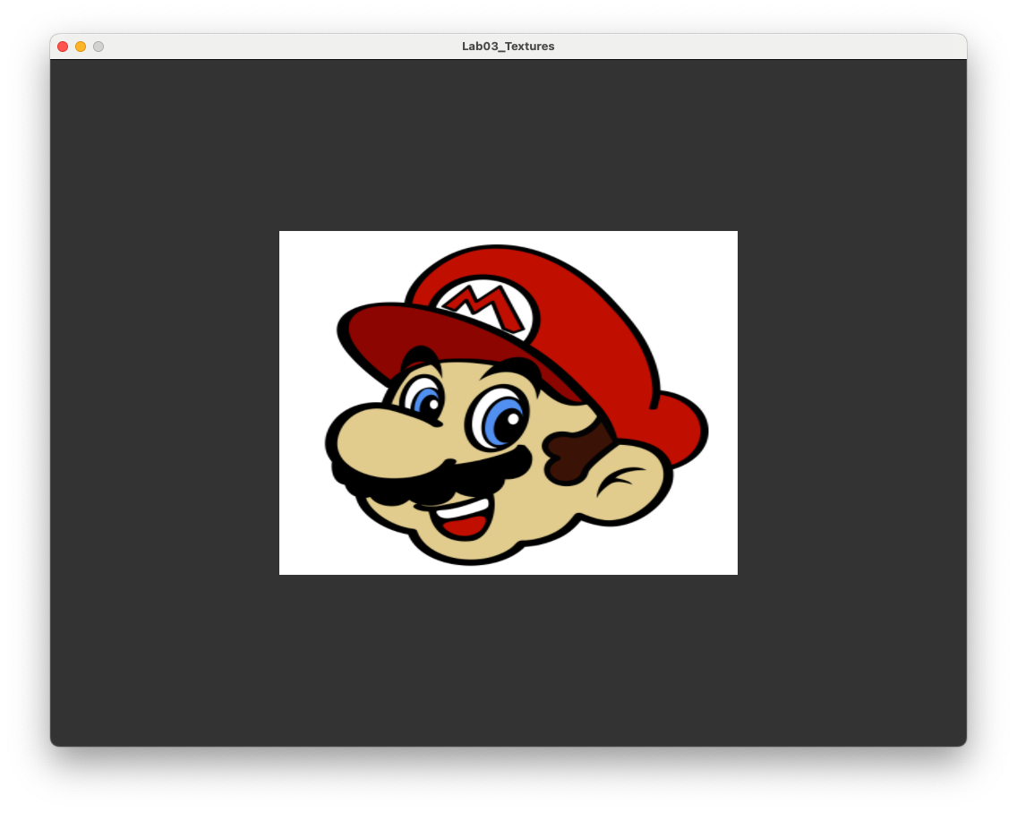
Fig. 3.7 Its a me, Mario!#
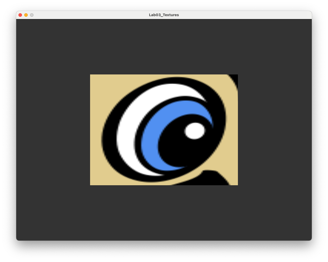
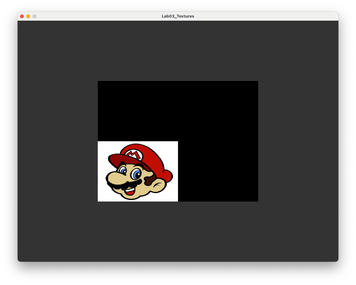
Now we can experiment with specifying texture co-ordinates outside of the range 0 to 1. Edit the uv array to change all of the 1.0f values to 2.0f. Compile and run the program and you should see the image shown in Fig. 3.8
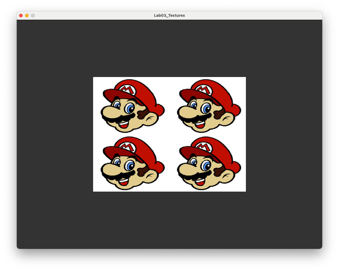
Fig. 3.8 Texture wrapping using GL_REPEAT.#
What has happened here as that OpenGL has used texture wrapping to repeated the texture over the rectangle (or more accurately the two triangles). This can be useful if we want to use a small texture containing a pattern over a larger polygon, e.g., think of brick wall where the pattern repeats itself.
OpenGL offers other options for texture wrapping;
GL_REPEAT- the texture repeats over the fragment (default);GL_MIRRORED_REPEAT- same asGL_REPEATbut the texture is mirrored with each repeat;GL_CLAMP_TO_EDGE- clamps the texture co-ordinates to between 0 and 1, co-ordinates outside of this range are clamped to the edge so that the textels on the edge are stretched to the edge of the fragment;GL_CLAMP_TO_BORDER- co-ordinates outside of the range \((0,0)\) to \((1,1)\) are given a used defined border colour.
We can specify the texture wrapping using the glTexParameteri() function. To apply GL_MIRRORED_REPEAT add the following code after the texture as been specified.
// Set texture wrapping options
glTexParameteri(GL_TEXTURE_2D, GL_TEXTURE_WRAP_S, GL_MIRRORED_REPEAT);
glTexParameteri(GL_TEXTURE_2D, GL_TEXTURE_WRAP_T, GL_MIRRORED_REPEAT);
Here we have specified the wrapping in the horizontal (S) and vertical (T) directions (some people, including as it seems the contributors to OpenGL, use \((s,t)\) for the vertex co-ordinates instead of the standard \((u,v)\)) to GL_MIRRORED_REPEAT. Compile and run the program and you should see the image shown in Fig. 3.9.
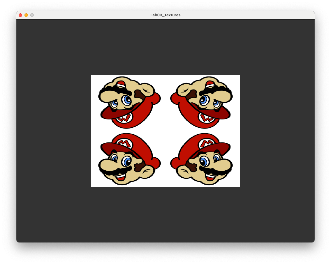
Fig. 3.9 Texture wrapping using GL_MIRRORED_REPEAT.#
Using GL_CLAMP_TO_EDGE and GL_CLAMP_TO_BORDER instead results in the images shown in Fig. 3.10 and Fig. 3.10.
3.3.2. Texture filtering#
Texture filtering is method of determining the colour of the fragment, known as the colour sample, from the texture. OpenGL maps the co-ordinates of the fragment to the texture co-ordinates and in most cases this will not align exactly to a textel centre, so what does OpenGL do? OpenGL provides two main options : nearest-neighbour interpolation and bilinear interpolation.
3.3.2.1. Nearest neighbour interpolation#
Nearest neighbour interpolation is the default in OpenGL uses the colour of the nearest textel to the texture co-ordinates as the colour sample. This is illustrated in the diagram shown in Fig. 3.12 where the texture co-ordinates represented by the black circle is mapped in a region on the texture with four neighbouring textels with the textel centres represented by the crosses. The texture co-ordinates are closest to the centre of the textel in the top-left so the colour of that textel is used for the colour sample.

Fig. 3.12 Nearest neighbour interpolation.#
To apply texture filtering we specify the type of interpolation we want in using glTexParameteri() functions. To apply nearest neighbour interpolation add the following code to your program.
glTexParameteri(GL_TEXTURE_2D, GL_TEXTURE_MIN_FILTER, GL_NEAREST);
glTexParameteri(GL_TEXTURE_2D, GL_TEXTURE_MAG_FILTER, GL_NEAREST);
The GL_TEXTURE_MIN_FILTER and GL_TEXTURE_MAG_FILTER arguments refer to minification and magnification. Minification is where the texture is larger than the polygon it is being mapped to so a fragment covers multiple textels. Magnification is the opposite where the texture is smaller than the polygon so that a single textel takes up multiple fragments. We can set different interpolation for magnification and minification.
To demonstrate the affects of minification lets use a low resolution texture. Change the path variable to the following.
// Load texture image from file
const char *path = "../assets/mario_small.png";
Compile and run the program and you should see the image shown in Fig. 3.13.

Fig. 3.13 Nearest neighbour interpolation#
As you can see the texture mapped rectangle has a block aliased look since multiple fragments share the same textel.
3.3.2.2. Bilinear interpolation#
Another method is to calculate the sample colour using bilinear interpolation where the distance between \((u,v)\) co-ordinate and the centre of a textel determines how much that textel contributes to the sample colour, i.e., the closer the textel the more of the textel colour is contained in the colour sample.

Fig. 3.14 Bilinear interpolation.#
To see the affects of bilinear interpolation, change GL_NEAREST to GL_LINEAR in the glTexParameteri() functions. Compile and run the program and you should see the image shown in Fig. 3.15.

Fig. 3.15 Nearest neighbour interpolation#
Here we have an improved texture mapping where the aliasing is less noticeable.
3.4. Mipmaps#
Another issue that may occur is when the fragment is a lot smaller than the texture which can happen when an object that is far away from the viewer. In these cases OpenGL will struggle to get the colour sample from a high resolution texture since a single fragment covers a large part of the texture.
To solve this issue OpenGL uses mipmaps (mip is short for the latin phrase “multum in parvo” or “much in little”) which are a series of textures, each one half the size of the previous one. OpenGL will use a mipmap texture most suitable based on the distance of the fragment from the viewer. This way the fragment does not span a large part of the texture and it also cuts down on memory.

Fig. 3.16 Mipmaps#
The good news is that we do not need to create lots of new different size textures because OpenGL has a function glGenerateMipmap() to do this for us which we have been using for a while.
One issue we may encounter is that when we switch between two mipmaps, e.g., when the viewer is moving towards or away from an object, there can be a notable change in appearance of the object. This is known as texture popping and is caused by switching between two mipmaps. To overcome this OpenGL gives the option to sample the texture from a linear interpolation between the two nearest mipmaps. So we have two main texture filtering options and two mipmap options giving four main mipmap options:
GL_NEAREST_MIPMAP_NEAREST- uses nearest texture filtering on the nearest mipmap;GL_LINEAR_MIPMAP_NEAREST- uses linear texture filtering on the nearest mipmap;GL_NEAREST_MIPMAP_LINEAR- uses nearest texture filtering on a linear interpolation between two mipmaps;GL_LINEAR_MIPMAP_LINEAR- uses linear texture filtering on a linear interpolation between two mipmaps.
Like with the texture filtering methods we can use different options for magnifying and minifying the texture. A popular combination is to use GL_LINEAR for the magnification filter and GL_LINEAR_MIPMAP_LINEAR for the minification filter to avoid textures popping as we zoom into a polygon.
glTexParameteri(GL_TEXTURE_2D, GL_TEXTURE_MAG_FILTER, GL_LINEAR);
glTexParameteri(GL_TEXTURE_2D, GL_TEXTURE_MIN_FILTER, GL_LINEAR_MIPMAP_LINEAR);
3.5. Multiple textures#
OpenGL allows us to use multiple textures in a single fragment shader (up to 16 in fact). For each new texture we use we need to create and bind the texture to a target, load the texture data from an image file and set the texture wrapping and filtering options. Rather than copying and pasting all of the code we have done for each new texture it makes sense to write a function that does this for us. Well if you look in the Lab03_Textures project, hidden away in the Header files folder is the file texture.hpp that contains a function loadTexture() that does all of the hard work for us (so why did I get you to do all of that coding above - I’m just evil I suppose mwahahahahaaa).
Comment out all of the code from the Lab03_Textures.cpp file you’ve written so far in this lab (or delete it if you are feeling a but annoyed) and enter the following code before the render loop.
// Load the textures
unsigned int texture1, texture2;
texture1 = loadTexture("../assets/crate.jpg");
texture2 = loadTexture("../assets/mario.png");
This loads the two textures we have been using which can be accessed using their targets texture1 and texture2. Compile and run the program and you should see the image from Fig. 3.5.
We now want to deal with two textures in the fragment shader so we need a way of telling OpenGL which texture is which, we do this using uniforms.
3.5.1. Uniforms#
A uniform is a shader variable that remains constant during the execution of the rendering pass and has the same value for all vertices and fragments. Uniforms provide a way to passing data to the shaders so we will use one for passing the texture target to the fragment shader.
Add the following code to your program before the render loop (since the textures are the same for every frame).
// Send the texture uniforms to the fragment shader
glUseProgram(shaderID);
unsigned int texture1ID, texture2ID;
texture1ID = glGetUniformLocation(shaderID, "texture1");
texture2ID = glGetUniformLocation(shaderID, "texture2");
glUniform1i(texture1ID, 0);
glUniform1i(texture2ID, 1);
Here we let OpenGL know we are using our shader program with the glUseProgram() function. We then get the location of two uniforms, called texture1 and texture2 respectively, and then assign the values of 0 and 1 to these uniforms using the glUniform1i() function. These values are the texture units that OpenGL uses to distinguish between the different textures in the fragment shader.
3.5.2. Texture units#
A texture unit is a location value used by fragment shader for the texture sampler we are using. The default texture unit for a texture is GL_TEXTURE0 which is what we have been using up to now. We can have up to 16 texture units, GL_TEXTURE0, GL_TEXTURE1 up to GL_TEXTURE15. Alternatively we could use GL_TEXTURE0, GL_TEXTURE0 + 1, GL_TEXTURE0 + 2 up to GL_TEXTURE + 15.
Add the following code before the render loop.
// Bind the textures
glActiveTexture(GL_TEXTURE0);
glBindTexture(GL_TEXTURE_2D, texture1);
glActiveTexture(GL_TEXTURE1);
glBindTexture(GL_TEXTURE_2D, texture2);
The glActiveTexture() function lets OpenGL know what texture unit we are currently dealing with and then we bind the texture to that unit using then glBindTexture() function.
3.5.3. Fragment shader#
The last thing we need to do is update the fragment shader so that it uses both textures. Modify fragmentShader.glsl so that is looks like the following.
#version 330 core

// Input
in vec2 UV;

// Output
out vec3 colour;

// Uniforms
uniform sampler2D texture1;
uniform sampler2D texture2;

void main()
{
    colour = vec3(mix(texture(texture1, UV), texture(texture2, UV), 0.7));
}
Here we have defined the two sampler2D uniforms texture1 and texture2, these need to be the same as what we called them in the glGetUniformLocation() functions. We then use the mix() function to combine the two textures so that 30% of the fragment colour is from the first texture (the crate) and the remaining 70% is from the second texture (Mario). Compile and run the program and you should see the image shown in Fig. 3.17.
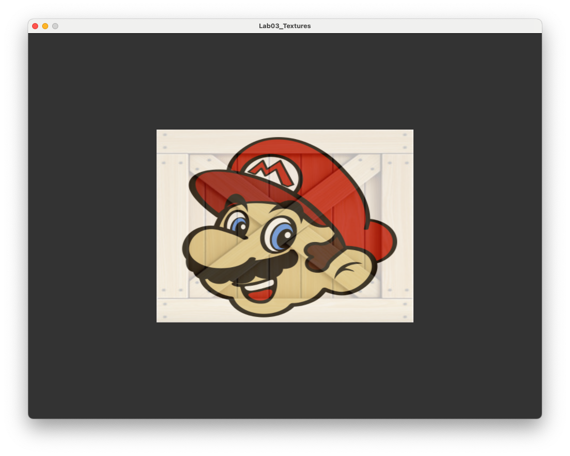
Fig. 3.17 A rectangle with a mix of two textures applied.#
3.6. Exercises#
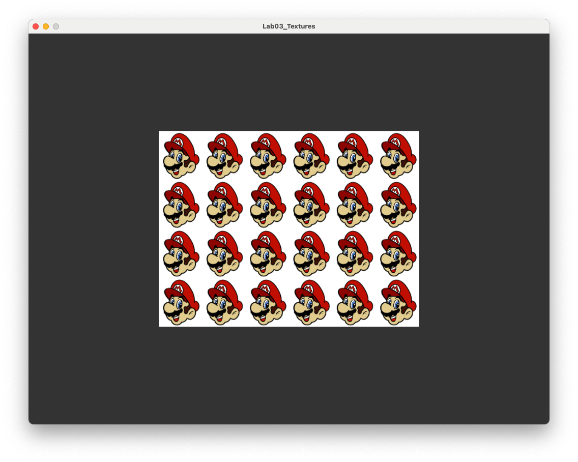
Change the
uvarray to create a texture rectangle consisting of a 6 by 4 grid of Marios.
Modify the fragment shader so that Mario is facing to the right instead of the left. Hint: the command
vec2(vector.x, vector.y)creates a 2-element vector using the elements ofvector.
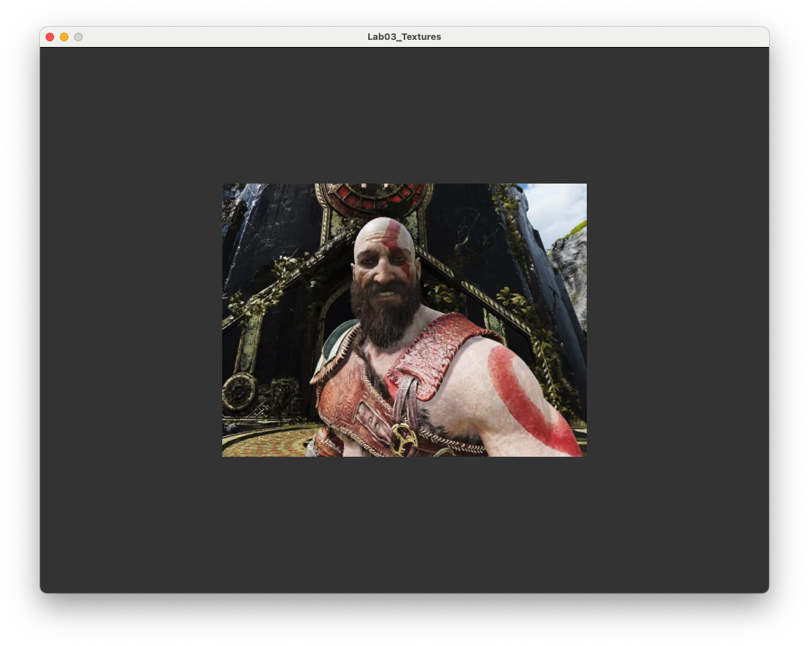
Apply a texture of your choice to the rectangle (e.g., a selfie).
Change the \((u,v)\) co-ordinates so that the textured rectangle shows a zoomed in image of Mario’s eye.