Lab 3: Textures#
Texture mapping is a technique for applying a 2D image known as a texture onto a 3D surface. Applying a texture adds detail and complexity to the appearance of 3D objects without the need for modelling intricate geometry.

Fig. 9 Mapping a texture to a polygon.#
The texture is a 2D image where each pixel within the texture, known as a textel, is referenced using the texture coordinates given as \((u,v)\) where \(u\) and \(v\) are in the range 0 to 1, i.e., \((0,0)\) corresponds to the textel in the bottom-left corner and \((1,1)\) corresponds to the textel in the top-right corner. When a fragment is created by the shader the corresponding texture coordinates are calculated and the sample colour of the textel is used for the fragment. Fortunately we do not need to write a texture mapper functions since these are in WebGL.
Task
Download Lab 3.zip and extract the files to your computer.
Load index.html in a live server, and you should see a colourful rectangle similar to the one you created in Lab 2: Basic Shapes in WebGL. We are going to apply a texture to this rectangle.
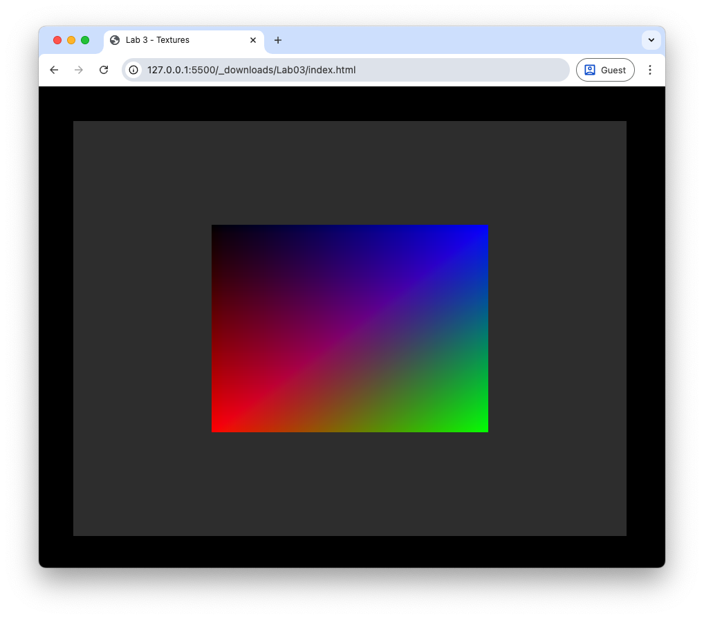
Fig. 10 A colourful rectangle.#
Creating a texture#
The first thing we need to do is create a texture in WebGL. We will do this by loading in an image file stored locally on our computer.
Task
Add the following function definition to the webGLUtils.js file.
function loadTexture(gl, url) {
  const texture = gl.createTexture();
  gl.bindTexture(gl.TEXTURE_2D, texture);
  gl.pixelStorei(gl.UNPACK_FLIP_Y_WEBGL, true);

  // Temporary 1×1 magenta pixel while image loads
  gl.texImage2D(gl.TEXTURE_2D, 0, gl.RGBA, 1, 1, 0, gl.RGBA, gl.UNSIGNED_BYTE, new Uint8Array([255, 0, 255, 255]));

  const image = new Image();
  image.src = url;
  image.onload = () => {
    gl.bindTexture(gl.TEXTURE_2D, texture);
    gl.texImage2D(gl.TEXTURE_2D, 0, gl.RGBA, gl.RGBA, gl.UNSIGNED_BYTE, image);
    gl.texParameteri(gl.TEXTURE_2D, gl.TEXTURE_MIN_FILTER, gl.LINEAR);
    gl.texParameteri(gl.TEXTURE_2D, gl.TEXTURE_MAG_FILTER, gl.LINEAR);
  };

  return texture;
}
Add the following code to the textures.js file after the VAO is created.
// Load texture
const texture = loadTexture(gl, "assets/mario.png");
Here we have defined a function loadTexture() that creates a texture object and loads an image from the specified URL into the texture. A temporary image consisting of a \(1 \times 1\) magenta pixel is used because WebGL needs something bound immediately even before the image has finished loading. Once the image has loaded it is copied into the texture using the gl.texImage2D() function. The texture filtering is set to linear interpolation for both minification and magnification using the gl.texParameteri() function (minification and magnification are explained later). We have then called this function to load in the image from the file mario.png in the assets folder.
Texture coordinates#
So we have created a texture and told WebGL all about it. Now we need to specify how we want to use the texture. To do this for each of the vertices of the triangle we need to define the corresponding \((u, v)\) texture coordinates where \((0, 0)\) is the bottom left-hand corner and \((1,1)\) is the top-right hand corner of the texture (see Fig. 9). We already have an array that contains the vertex coordinates and colours, so we can simply add \((u, v)\) coordinates to this.
Task
Edit the vertices array so that the \((u,v)\) coordinates are defined for each vertex.
// Define vertices
const vertices = new Float32Array([
  // x    y    z       R    G    B       u    v
  -0.5, -0.5, 0.0,    1.0, 0.0, 0.0,    0.0, 0.0, // vertex 0  3 -- 2
   0.5, -0.5, 0.0,    0.0, 1.0, 0.0,    1.0, 0.0, // vertex 1  |  / |
   0.5,  0.5, 0.0,    0.0, 0.0, 1.0,    1.0, 1.0, // vertex 2  | /  |
  -0.5,  0.5, 0.0,    1.0, 1.0, 1.0,    0.0, 1.0, // vertex 3  0 -- 1
]);
Here we have defined the texture coordinates for each vertex so that each vertex of the rectangle is mapped to the corresponding vertex of the texture. Now that we have added texture coordinates to each vertex we need to update the code that tells WebGL how to interpret the data in the vertex buffer.
Task
In the createVao() function in the webGLUtils.js file, update the stride value.
const stride = 8 * Float32Array.BYTES_PER_ELEMENT;
And add the following before the VAO is unbound.
// Texture coordinates
offset = 6 * Float32Array.BYTES_PER_ELEMENT;
const texCoordsLocation = gl.getAttribLocation(program, "aTexCoord");
gl.enableVertexAttribArray(texCoordsLocation);
gl.vertexAttribPointer(texCoordsLocation, 2, gl.FLOAT, false, stride, offset);
Shaders#
The next thing we need to do is to update the vertex and fragment shader. The texture coordinates are read in by the vertex shader and then passed to the rasteriser which calculates the texture coordinates of each fragment.
Task
Add an input and output declaration to the vertex shader.
in vec2 aTexCoord;


out vec2 vTexCoord;
Then in the main() function in the vertex shader add the following.
// Output texture co-ordinates
vTexCoord = aTexCoord;
Here we declare a 2-element input vector aTexCoord and a 2-element output vector vTexCoord for the texture coordinates of the vertex (recall that standard convention is that the prefix a stands for attribute and v stands for varying). The texture coordinates are outputted without us doing anything to them.
The fragment shader needs to read in the texture coordinates of the fragment and get the colour of the fragment from the texture.
Task
Add the following input declaration to the fragment shader.
in vec2 vTexCoord;
And add the following uniform declaration before the main() function in the fragment shader.
uniform sampler2D uTexture;
Then in the main() function in the fragment shader edit the code used to determine the fragment colour to the following.
fragColour = texture(uTexture, vTexCoord);
Here we have an input of the 2-element vector vTexCoord which has been outputted from the vertex shader. This contains the \((u,v)\) coordinates of the fragment which has been calculated by WebGL by interpolating between the three triangle vertices. A uniform is declared which is a sampler2D type called uTexture. A uniform is a shader variable that remains constant during the execution of the rendering pass and has the same value for all vertices and fragments. Uniforms provide a way to passing data to the shaders which we have done here with our texture. The colour of the fragment is taken from the texture using the texture() function which outputs a 4-element RGBA vector.
The last thing we need to do is to bind the texture to the uniform in the JavaScript code.
Task
Add the following code before we draw the rectangle
// Bind texture
gl.activeTexture(gl.TEXTURE0);
gl.bindTexture(gl.TEXTURE_2D, texture);
gl.uniform1i(gl.getUniformLocation(program, "uTexture"), 0);
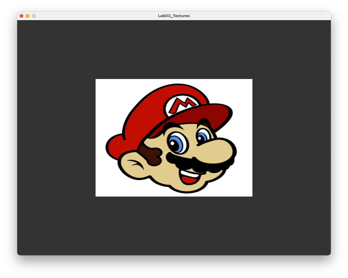
Refresh your web browser, and you should see that we now have applied a texture to the rectangle.
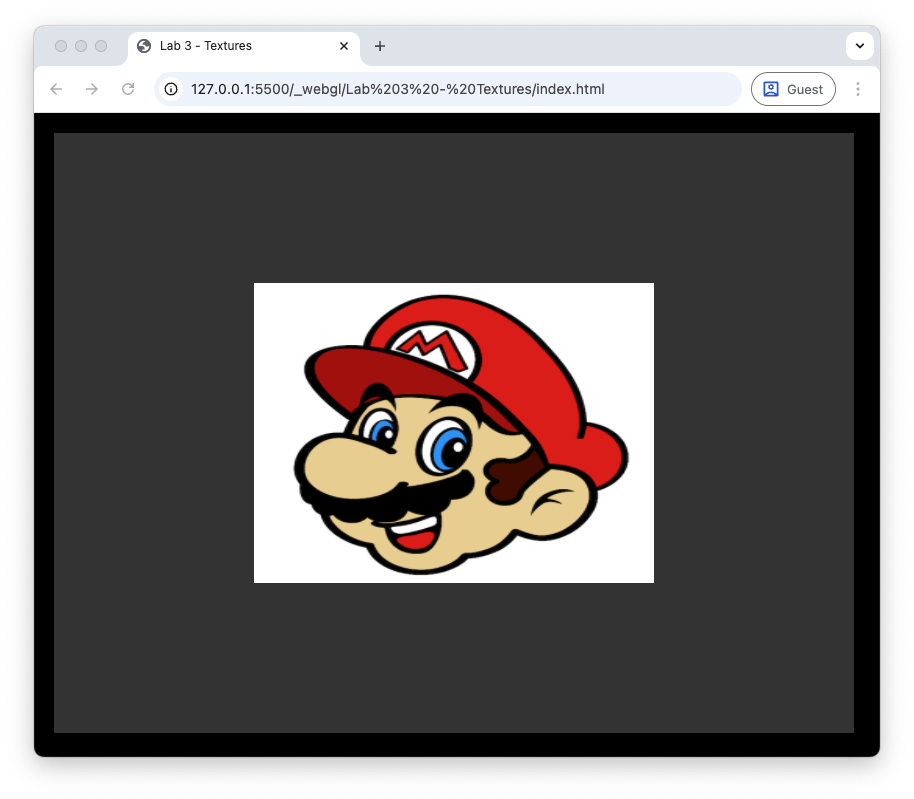
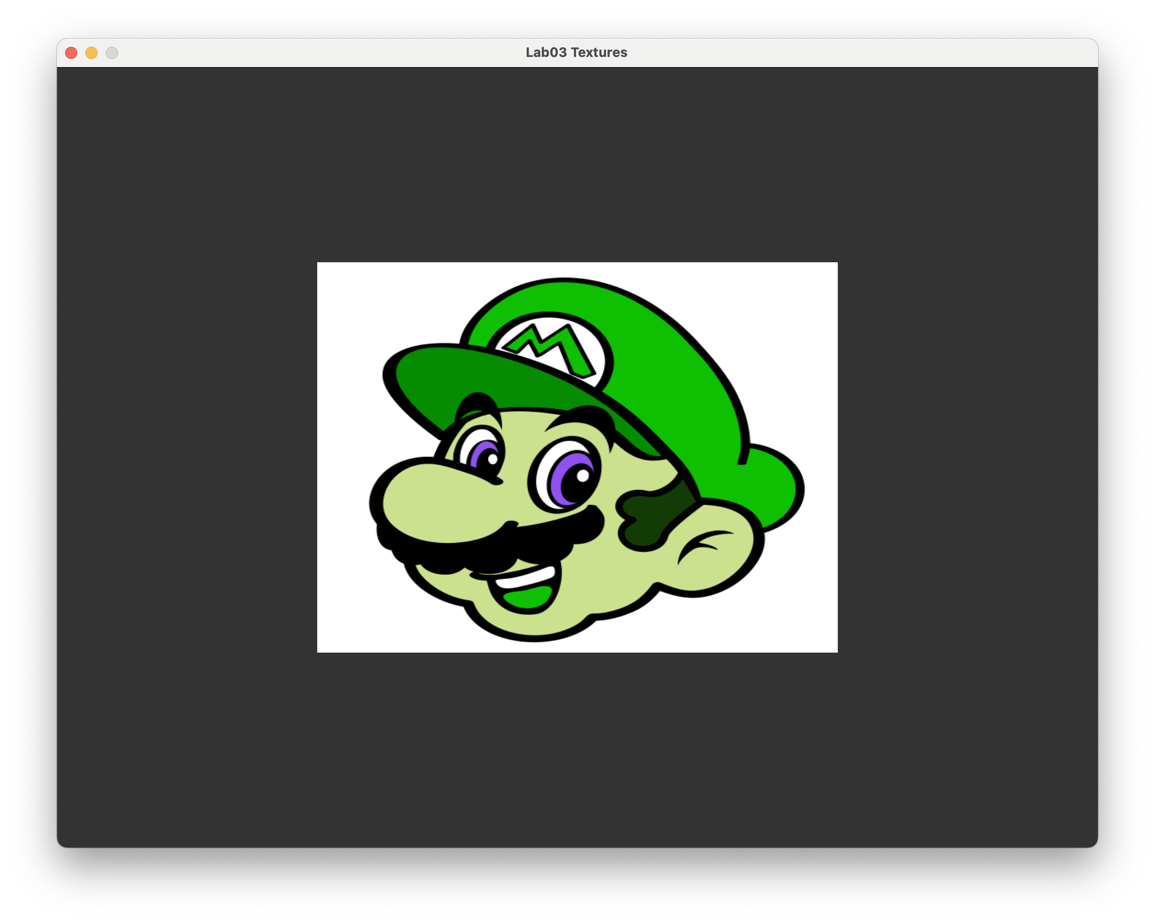
Fig. 11 It’s a me, Mario!#
Texture filtering#
When we apply a texture to a polygon, WebGL needs to determine the colour of each fragment from the texture. This is not always straightforward since the size of the texture and the size of the polygon may not match up. For example, if the texture is very high resolution and the polygon is small on the screen then a single fragment may cover multiple textels in the texture. Conversely, if the texture is low resolution and the polygon is large on the screen then a single textel may cover multiple fragments. To deal with these issues WebGL scales the texture.
There are two types of scaling:
Minification - where the texture is larger than the polygon it is being mapped to so a fragment covers multiple textels, so the texture must be minified to fit the polygon;

Magnification - where the texture is smaller than the polygon so that a single textel takes up multiple fragments, so the texture must be magnified to fit the polygon.

In addition to scaling the texture WebGL also needs to determine how to get the colour of the fragment from the texture. There are different methods for doing this known as texture filtering.
There are two types of texture filtering:
Nearest-neighbour interpolation - where the colour of the nearest textel to the \((u,v)\) texture coordinates is used as the colour sample.

Fig. 12 Nearest neighbour interpolation.#
Bilinear interpolation - where the distance between \((u,v)\) coordinate and the centre of a textel determines how much that textel contributes to the colour sample.

Fig. 13 Bilinear interpolation.#
In our loadTexture() function we set the texture filtering to linear interpolation for both minification and magnification using the following code.
gl.texParameteri(gl.TEXTURE_2D, gl.TEXTURE_MIN_FILTER, gl.LINEAR);
gl.texParameteri(gl.TEXTURE_2D, gl.TEXTURE_MAG_FILTER, gl.LINEAR);
Here we specified that both minification and magnification should use bilinear interpolation. We can change these settings to see how they affect the appearance of the texture on the rectangle.
Task
Chnage the command to load the texture in the textures.js file to the following.
// Load texture
const texture = loadTexture(gl, "assets/mario_small.png");
In the loadTexture() function in the webGLUtils.js file, change the texture filtering to nearest-neighbour interpolation for both minification and magnification using the following code.
gl.texParameteri(gl.TEXTURE_2D, gl.TEXTURE_MIN_FILTER, gl.NEAREST);
gl.texParameteri(gl.TEXTURE_2D, gl.TEXTURE_MAG_FILTER, gl.NEAREST);
Here we have changed the texture to a low resolution \(64 \times 64\) pixel version of the Mario texture and the texture filtering to nearest-neighbour interpolation. Refresh your web browser, and you should see the image shown in Fig. 14.
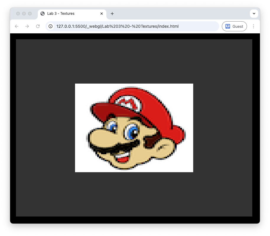
Fig. 14 Nearest neighbour interpolation#
We have told WebGL to use the nearest textel to get the colour sample for each fragment. This results in a blocky appearance since each textel is enlarged to cover multiple fragments.
Task
Change the texture filtering back to bilinear interpolation for both minification and magnification.
Refresh your web browser, and you should see the image shown in Fig. 15. Here we have told WebGL to use bilinear interpolation to get the colour sample for each fragment. This results in a smoother appearance since the colours of multiple textels are blended together to get the colour sample for each fragment. Our texture mapped rectangle looks slightly blurry since we are using a low resolution texture.

Fig. 15 Bilinear interpolation#
Mipmaps#
Another issue that may occur is when the fragment is a lot smaller than the texture which can happen when an object that is far away from the viewer. In these cases WebGL will struggle to get the colour sample from a high resolution texture since a single fragment covers a large part of the texture.
To solve this issue WebGL uses mipmaps (mip is short for the latin phrase “multum in parvo” or “much in little”) which are a series of textures, each one half the size of the previous one. WebGL will use a mipmap texture most suitable based on the size of the fragment relative to the texture. This way the fragment does not span a large part of the texture.

Fig. 16 Mipmaps#
The good news is that we do not need to create lots of new different size textures because WebGL has a function glGenerateMipmap() to do this for us. The bad news is that we can only use this when the dimensions of the texture image are powers of two, e.g., \(64 \times 64\), \(128 \times 128\), \(256 \times 256\) etc. When we have non-power of 2 textures we cannot use mipmaps.
One issue we may encounter is that when we switch between two mipmaps, e.g., when the viewer is moving towards or away from an object, there can be a notable change in appearance of the object. This is known as texture popping and is caused by switching between two mipmaps. To overcome this WebGL gives the option to sample the texture from a linear interpolation between the two nearest mipmaps. So we have two main texture filtering options and two mipmap options giving four main mipmap options:
Setting |
Description |
|---|---|
|
uses nearest texture filtering on the nearest mipmap |
|
uses linear texture filtering on the nearest mipmap |
|
uses nearest texture filtering on a linear interpolation between two mipmaps |
|
uses linear texture filtering on a linear interpolation between two mipmaps |
Task
Add the following function definition to the webGLUtils.js file.
function isPowerOf2(x) {
    return (x & (x - 1)) === 0;
}
Then change the onlload function in the loadTexture() function to the following.
image.onload = () => {
  gl.bindTexture(gl.TEXTURE_2D, texture);
  gl.texImage2D(gl.TEXTURE_2D, 0, gl.RGBA, gl.RGBA, gl.UNSIGNED_BYTE, image);

  // Auto-generate mipmaps (requires power-of-2 image)
  if (isPowerOf2(image.width) && isPowerOf2(image.height)) {
    gl.generateMipmap(gl.TEXTURE_2D);
    gl.texParameteri(gl.TEXTURE_2D, gl.TEXTURE_MIN_FILTER, gl.LINEAR_MIPMAP_LINEAR);
    gl.texParameteri(gl.TEXTURE_2D, gl.TEXTURE_MAG_FILTER, gl.LINEAR);
  } else {
    // Non power-of-2 textures must be clamped & non-mipmapped
    gl.texParameteri(gl.TEXTURE_2D, gl.TEXTURE_MIN_FILTER, gl.LINEAR);
    gl.texParameteri(gl.TEXTURE_2D, gl.TEXTURE_MAG_FILTER, gl.LINEAR);
    gl.texParameteri(gl.TEXTURE_2D, gl.TEXTURE_WRAP_S, gl.CLAMP_TO_EDGE);
    gl.texParameteri(gl.TEXTURE_2D, gl.TEXTURE_WRAP_T, gl.CLAMP_TO_EDGE);
  }
};
Now revert the texture back to the high resolution version by changing the load command.
const texture = loadTexture(gl, "assets/mario.png");
Here we have created a function to check if a number is a power of 2 and used this in the onload function to decide whether we can generate mipmaps or not. Refresh your web browser, and you should see the image similar to that from Fig. 11.
Texture wrapping#
In our examples above, all the texture coordinates have been in the range from 0 to 1. What happens if we use textures coordinates outside this range?
Task
Change the texture coordinates in the vertices array so that in the \((u,v)\) coordinates, the 1.0 are changed to 4.0
// Define vertices
const vertices = new Float32Array([
    // x    y    z       R    G    B       u    v
    -0.5, -0.5, 0.0,    1.0, 0.0, 0.0,    0.0, 0.0, // vertex 0  3 -- 2
     0.5, -0.5, 0.0,    0.0, 1.0, 0.0,    4.0, 0.0, // vertex 1  |  / |
     0.5,  0.5, 0.0,    0.0, 0.0, 1.0,    4.0, 4.0, // vertex 2  | /  |
    -0.5,  0.5, 0.0,    1.0, 1.0, 1.0,    0.0, 4.0, // vertex 3  0 -- 1
]);
Refresh your web browser, and you see something like the following.
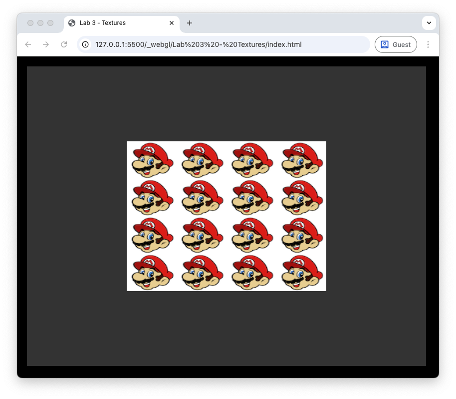
Fig. 17 Texture wrapping using GL_REPEAT.#
Here WebGL has used texture wrapping to repeat the texture over the rectangle. This can be useful if we want to use a small texture containing a pattern over a larger polygon, e.g., think of brick wall where the pattern repeats itself. WebGL offers other options for texture wrapping;
Setting |
Description |
|---|---|
|
the texture repeats over the fragment (default) |
|
same as |
|
clamps the texture coordinates to between 0 and 1, coordinates outside this range are clamped to the edge so that the textels on the edge are stretched to the edge of the fragment |
The WebGL default wrapping is GL_REPEAT but we can specify the texture wrapping using the glTexParameteri() function.
Task
Add the following to the loadTexture() function in the webGLUtils.js file after the mipmap if statement.
gl.texParameteri(gl.TEXTURE_2D, gl.TEXTURE_WRAP_S, gl.MIRRORED_REPEAT);
gl.texParameteri(gl.TEXTURE_2D, gl.TEXTURE_WRAP_T, gl.MIRRORED_REPEAT);
Here we have specified the wrapping in the horizontal (S) and vertical (T) directions (some people use \((S,T)\) for the vertex coordinates instead of \((u,v)\)) to GL_MIRRORED_REPEAT. Refresh your web browser, and you should see the image shown below.
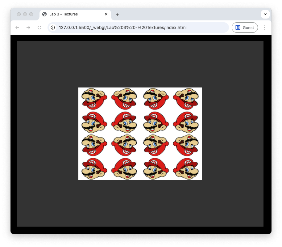
Fig. 18 Texture wrapping using GL_MIRRORED_REPEAT.#
Using GL_CLAMP_TO_EDGE results in the images shown below.
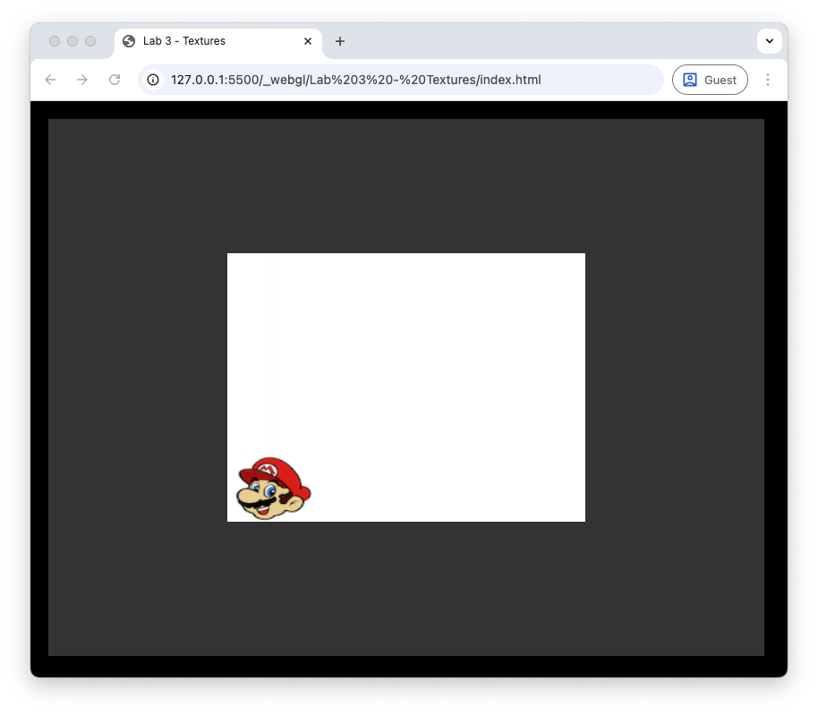
Fig. 19 Texture wrapping using GL_CLAMP_TO_EDGE.#
Multiple textures#
WebGL allows us to use up to 16 textures in a single fragment shader. For each new texture we use we need to create and bind the texture to a target, load the texture data from an image file and set the texture wrapping and filtering options.
A texture unit is a location value used by fragment shader for the texture sampler we are using. The default texture unit for a texture is GL_TEXTURE0 which is what we have been using up to now. We can have up to 16 texture units, GL_TEXTURE0, GL_TEXTURE1 up to GL_TEXTURE15. Alternatively we could use GL_TEXTURE0, GL_TEXTURE0 + 1, GL_TEXTURE0 + 2 up to GL_TEXTURE + 15.
Task
Load a second texture by adding the following code after the first texture is loaded
const texture2 = loadTexture(gl, "assets/crate.png");
And add the following code in the render() function after we bound the Mario texture
gl.activeTexture(gl.TEXTURE1);
gl.bindTexture(gl.TEXTURE_2D, texture2);
gl.uniform1i(gl.getUniformLocation(program, "uTexture2"), 1);
Here we have loaded a second texture from the file crate.png in the assets folder. We then bind this texture to the second texture unit GL_TEXTURE1 and bind this to a uniform called uTexture2 in the fragment shader. We now need to update the fragment shader to use both textures.
Task
In the fragment shader, add the following after we have declared the first texture uniform.
uniform sampler2D uTexture2;
And then modify the fragment colour assignment to the following.
fragColour = mix(texture(uTexture, vTexCoord), texture(uTexture2, vTexCoord), 0.4);
Here we have used the mix() function to combine the two textures so that 60% is from the first texture (Mario) and the and the remaining 40% is from the second texture (the crate).
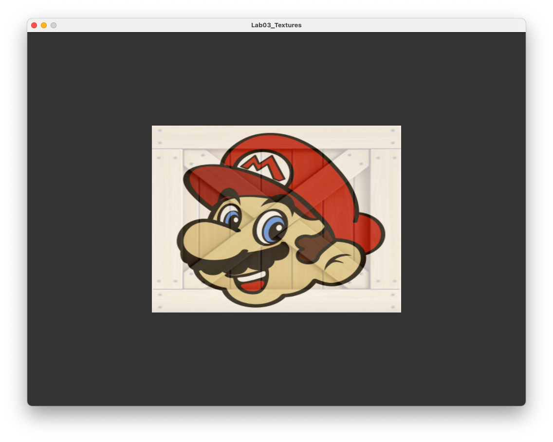
Fig. 20 A rectangle with a mix of two textures applied.#
Exercises#
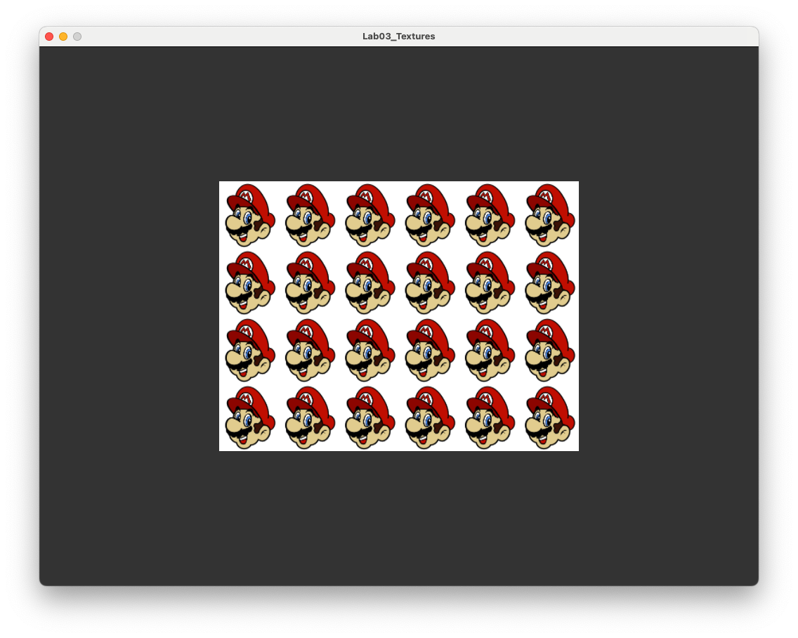
Change the
uvarray to create a texture rectangle consisting of a 6 by 4 grid of Mario’s.
Modify the fragment shader so that Mario is facing to the right instead of the left. Hint: the command
vec2(vector.x, vector.y)creates a 2-element vector using the elements ofvector.
Modify the fragment shader so that the red and green colour components of the pixel are switched. Hint: you can use swizzling for RGBA components, e.g.,
vector.rreturns the red colour component of the 4-element vectorvector.
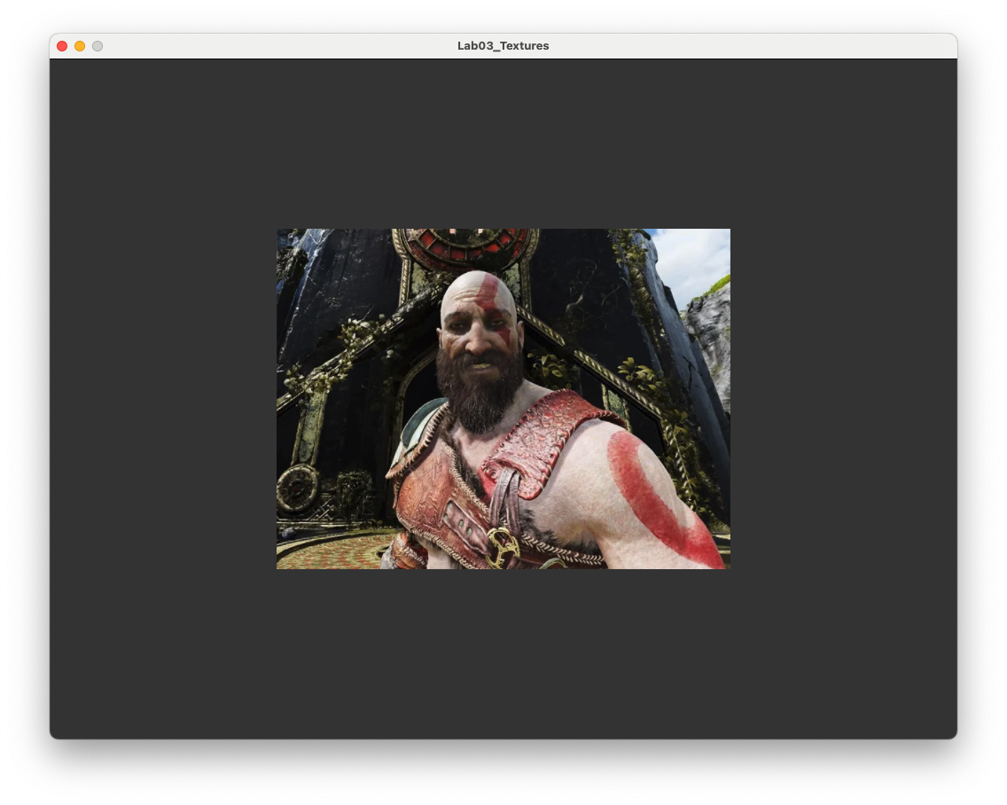
Apply a texture of your choice to the rectangle (e.g., a selfie or a picture of cute kitten).
Modify the fragment shader so that the colours of the vertices are multiplied by the Mario texture.
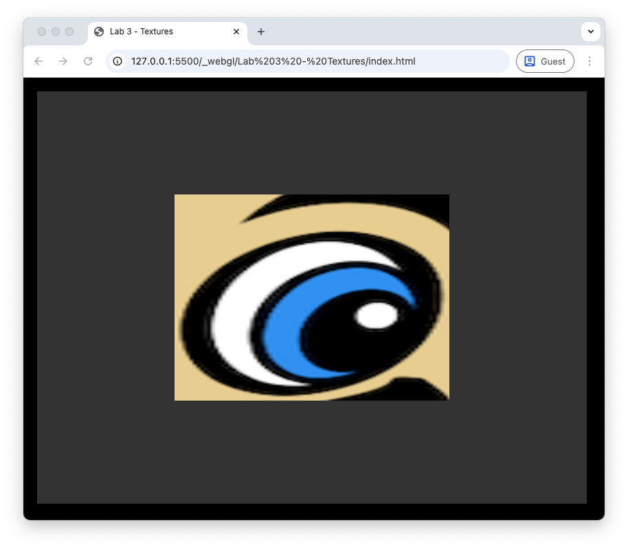
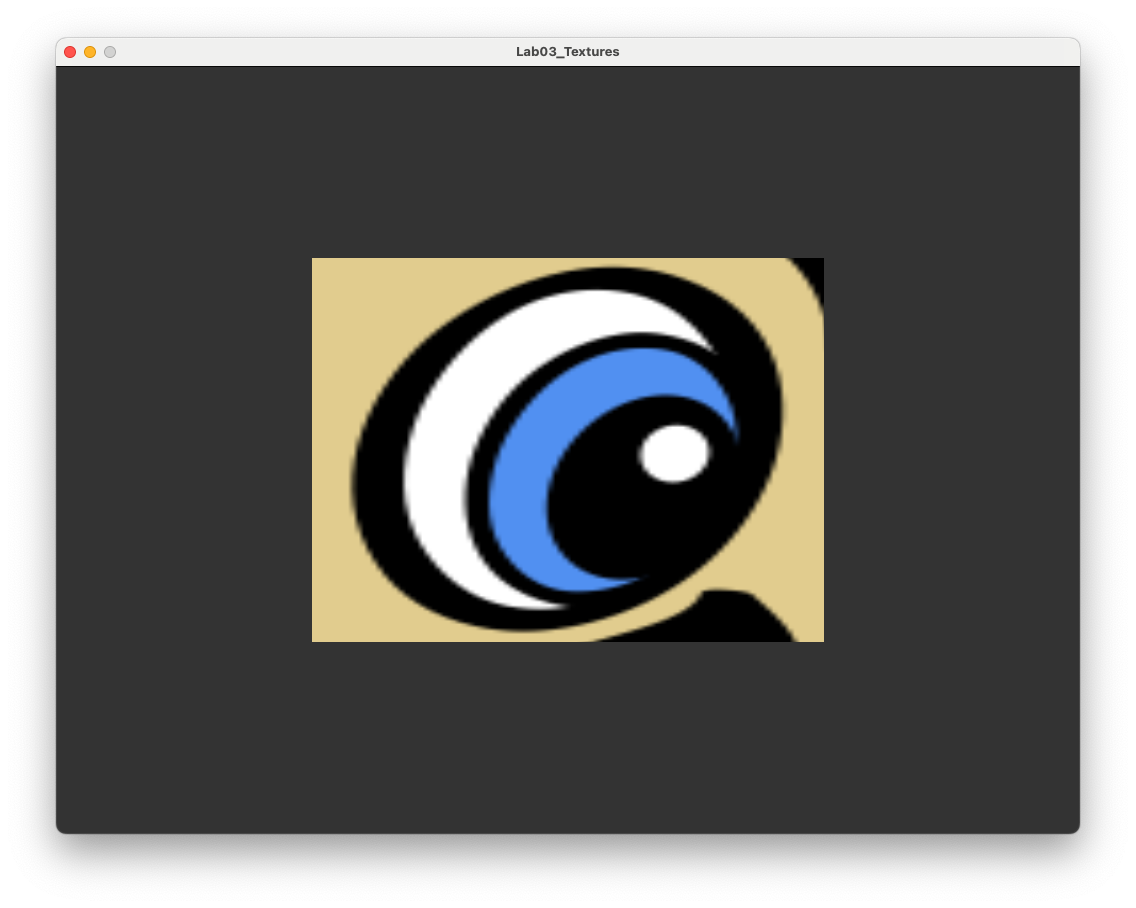
Change the \((u,v)\) coordinates so that the textured rectangle shows a zoomed in image of Mario’s eye.