Lab 2: Colours#
In the previous page we were able to draw triangles using WebGL of a single colour. Whilst this is awesome, wouldn’t it be better if we were able to draw triangles using different colours. In this page we will see how we can add colour data to each vertex, add more shapes to the scene and make use of VAOs (Vertex Array Objects) and EBOs (Element Buffer Objects).
Hello Colourful Triangle#
We are going to build upon the code we used to draw the boring red triangle example and jazz it up a bit by defined colour data for each vertex. Instead of starting from scratch, let’s copy the code from the previous page.
Task
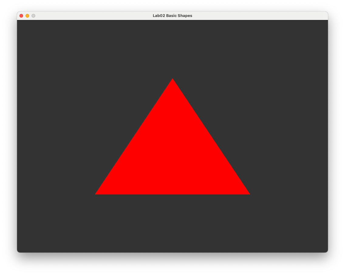
Create a folder called 02 Colours and download index.html, colours.js and webGLUtils.js to it. Open index.html in a web browser to check that the red triangle from Lab 1 is displayed.
Recall that the basic steps to draw the hello triangle were
Write and compile a vertex and fragment shader and link these in a WebGL program.
Create a vertex buffer on the GPU and copy across vertex co-ordinate data from the CPU.
Tell WebGL how to read the vertex buffer.
Tell WebGL to draw the triangle.
To add colour data to our triangle we need to modify the vertex and fragment shaders to work with an additional input of colour data, add a buffer containing the colours of the vertices and tell WebGL how to read this buffer.
Vertex and Fragment Shaders#
Our current vertex shader simply takes in an input of a 3-element vector containing the \((x, y, z)\) vertex co-ordinates and outputs a 4-element vector of these co-ordinates to the fragment shader. The vertex co-ordinates are outputted using the gl_Position variable which is a required output and is not specifically declared. To add colour data to our co-ordinates we need to declare a second 3-element input vector for the attribute colour as well as an output vector for the vertex colour. So our vertex shader is
#version 300 es
precision mediump float;

in vec3 aPosition;
in vec3 aColour;

out vec3 vColour;

void main() {
  gl_Position = vec4(aPosition, 1.0);

  // Output fragment colour
  vColour = aColour;
}
As for the fragment shader, we will simply output the colour data of the vertex. Our current fragment shader does not have an input declared because it expects gl_Position by default, so we need to add an input declaration for the vertex colour outputted by the vertex shader and use this to create the 4-element RGBA output vector.
#version 300 es
precision mediump float;

in vec3 vColour;

out vec4 outColour;

void main() {
  outColour = vec4(vColour, 1.0);
}
Task
Edit the vertex shader code at the top of the colours.js file so that is contains the modified vertex and fragment shaders shown above.
Vertex Colours#
To add colour data to the triangle vertices we add 3 more float values for the red, green and blue colours to the triangleVertices array.
Task
Amend the triangleVertices array so that it looks like the following.
// Define triangle vertices
const triangleVertices = new Float32Array([
  // x     y    z        r    g    b
   -0.5, -0.5, 0.0,     1.0, 0.0, 0.0, // vertex 0       2
    0.5, -0.5, 0.0,     0.0, 1.0, 0.0, // vertex 1     /   \
    0.0,  0.5, 0.0,     0.0, 0.0, 1.0, // vertex 2    0 --- 1
]);
Here we have specified vertex 0 is pure red, vertex 1 is pure green and vertex 2 is pure blue. If you refresh your web browser you should see that the red triangle is now black, and it appears that the top vertex has been moved to the right-hand edge of the canvas (black-triangle-figure). The reason why its skewed is that when we told WebGL how to read the vertex buffer using gl.vertexAttribPointer(colourLocation, 3, gl.FLOAT, false, 0, 0);. This means that WebGL is expected no gaps between the vertex co-ordinate data since the stride input (the second to last input) is 0, so it thinks the 3 vertex co-ordinates are \((-0.5, -0.5, 0)\), \((1, 0, 0)\) and \((0.5, -0.5, 0)\).
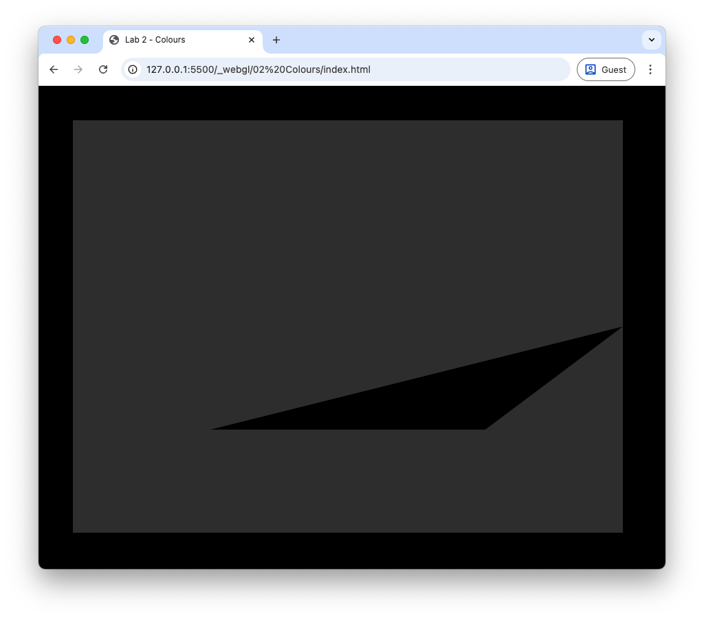
Fig. 4 Oops, something has gone wrong.#
This is where the stride input for the gl.vertexAttribPointer() function comes in. Stride is the number of bytes from the start of the attribute (in our case the \(x\) vertex co-ordinate) for one vertex to the start of the same attribute of the next vertex. We added 3 floats for the RGB data, so our stride is the number of bytes used to store 6 float values, i.e., 3 for the \((x, y, z)\) values and 3 for the RGB values.

Fig. 5 The stride and offset of a vertex array.#
Task
Change the gl.vertexAttribPointer(); function so that it looks like the following.
gl.vertexAttribPointer(
  positionLocation,                   // index
  3,                                  // size
  gl.FLOAT,                           // type
  false,                              // normalized
  6 * Float32Array.BYTES_PER_ELEMENT, // stride
  0);                                 // offset
Refresh your browser, and you should see that the triangle vertices has returned to its previous state, but it’s still black (Sorted the vertex co-ordinates but not the colour.). The reason for this is that we have not yet told WebGL about our new vertex colours. To do this we get the location of the aColour attribute from the vertex shader, enable the attribute array and point WebGL to where it can find the colour data.
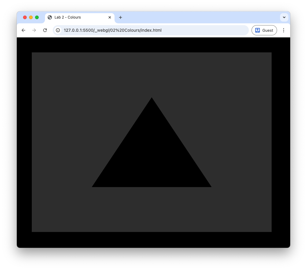
Fig. 6 Sorted the vertex co-ordinates but not the colour.#
Task
Enter the following code after we told WebGL how to read the co-ordinate data.
const colourLocation = gl.getAttribLocation(shaderProgram, 'aColour');
gl.enableVertexAttribArray(colourLocation);
gl.vertexAttribPointer(
  colourLocation,                      // index
  3,                                   // size
  gl.FLOAT,                            // type
  false,                               // normalized
  6 * Float32Array.BYTES_PER_ELEMENT,  // stride
  3 * Float32Array.BYTES_PER_ELEMENT); // offset
Note that here the offset value is 3 lots of the number of bytes used to store a 32-bit float. This is because the colour data comes after the 3 floats for the co-ordinate values.
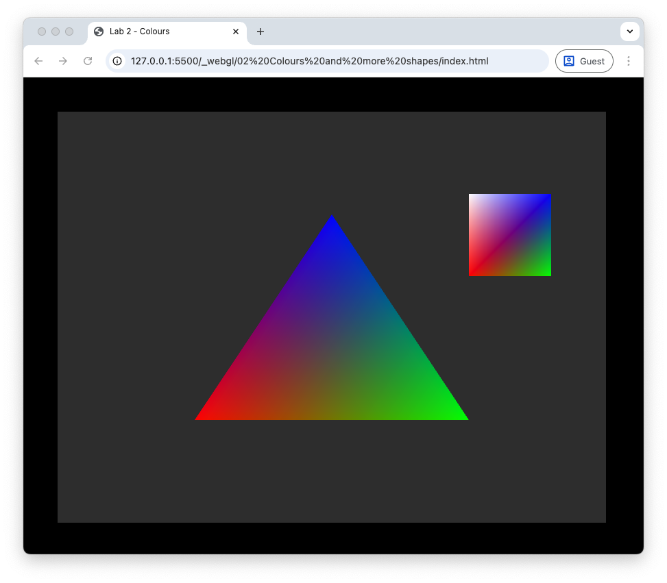
Refresh your browser you should see the triangle in all its glorious colourfulness.
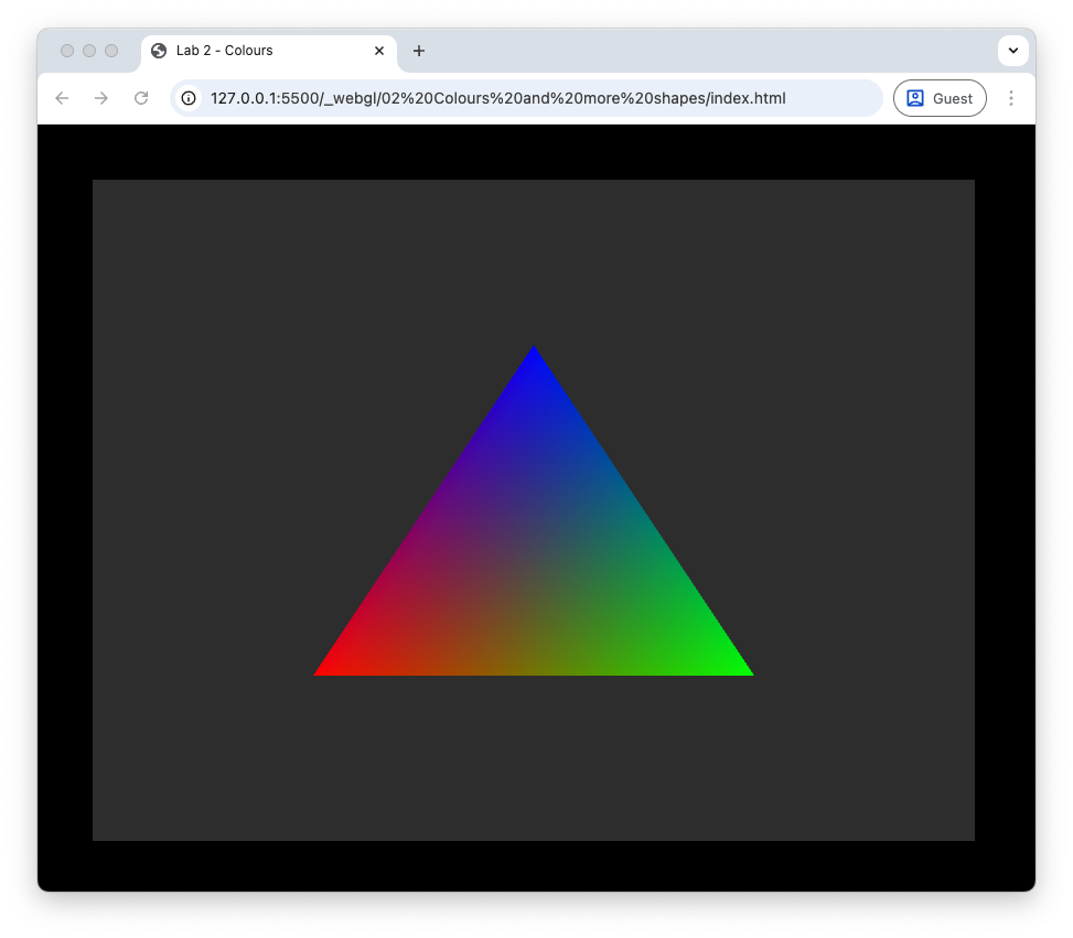
Fig. 7 Hello colourful triangle!#
You can see that the 3 triangle vertices are red, green and blue going anti-clockwise from the bottom-left vertex. The colour of the pixels across the interior of the triangle have been interpolated by the rasteriser so that we have a smooth transition of colours.
More Shapes#
To keep our colourful triangle company we are going to introduce another shape, a square, to our scene. In most graphics applications shapes are constructed using triangle primitives. Triangles are the simplest 2D shape and all other shapes are constructed using triangles. So to construct a square we need two triangles.
Task
Enter the following code after we defined the triangle vertex buffer.
// Define square vertices
const squareVertices = new Float32Array([
  // x    y    z       r    g    b
    0.5, 0.2, 0.0,    1.0, 0.0, 0.0, // vertex 0     3 -- 2
    0.8, 0.2, 0.0,    0.0, 1.0, 0.0, // vertex 1     |  / |
    0.8, 0.6, 0.0,    0.0, 0.0, 1.0, // vertex 2     | /  |
    0.5, 0.2, 0.0,    1.0, 0.0, 0.0, // vertex 0     0 -- 1
    0.8, 0.6, 0.0,    0.0, 0.0, 1.0, // vertex 2
    0.5, 0.6, 0.0,    1.0, 1.0, 1.0, // vertex 3
]);

// Create VBO for the square
const squareVBO = gl.createBuffer();
gl.bindBuffer(gl.ARRAY_BUFFER, squareVBO);
gl.bufferData(gl.ARRAY_BUFFER, squareVertices, gl.STATIC_DRAW);
gl.bindBuffer(gl.ARRAY_BUFFER, null);
Here we have defined the co-ordinates and colours for vertices of a square. We are using 2 triangles to construct the square, so we have 6 vertices in total. Like with the triangle, we have also created a vertex buffer for the square and copied the data across to the GPU. We now need to tell WebGL how to read the square vertex buffer and to draw the 2 triangles that make up the square.
Task
Enter the following code after we have drawn the triangle.
// Tell WebGL how to read data from the square vertex buffer
gl.bindBuffer(gl.ARRAY_BUFFER, squareVBO);
gl.enableVertexAttribArray(positionLocation);
gl.vertexAttribPointer(positionLocation, 3, gl.FLOAT, false, 6 * Float32Array.BYTES_PER_ELEMENT, 0);
gl.enableVertexAttribArray(colourLocation);
gl.vertexAttribPointer(colourLocation, 3, gl.FLOAT, false, 6 * Float32Array.BYTES_PER_ELEMENT, 3 * Float32Array.BYTES_PER_ELEMENT);

// Draw the square
gl.drawArrays(gl.TRIANGLES, 0, 6);
This is very similar to what we did for the triangle object, i.e., we bind the vertex buffer for the square, enable the vertex attribute array and tell WebGL where the data is. Note that we already know the location of the position and colour attributes. Since we are drawing two squares, we change the 3 to a 6 in the gl.drawArrays() function.
Vertex Array Objects (VAO)#
You may have noticed that telling WebGL how to read the VBOs for both the triangle and square objects required repetition of code. Every time we draw a different object we are repeating this code, with just 2 objects this isn’t too bad, but when we are dealing with hundreds of objects it will become unmanageable. A Vertex Array Object (VAO) is a WebGL object that stores all the state related to the vertex, i.e., vertex attributes and bindings to attribute locations, so that once it is set up we only need a single block of code to bind the VAO and draw the object.
Task
Delete (or comment out) the code used to tell WebGL how to interpret the vertex buffers for the triangle and square as well as the draw command.
Enter the following code after we have created the shader program.
// Get attribute locations
const positionLocation = gl.getAttribLocation(shaderProgram, "aPosition");
const colourLocation = gl.getAttribLocation(shaderProgram, "aColour");

// Create VAO for the triangle
const triangleVAO = gl.createVertexArray();
gl.bindVertexArray(triangleVAO);
gl.bindBuffer(gl.ARRAY_BUFFER, VBO);
gl.enableVertexAttribArray(positionLocation);
gl.vertexAttribPointer(positionLocation, 3, gl.FLOAT, false, 6 * Float32Array.BYTES_PER_ELEMENT, 0);
gl.enableVertexAttribArray(colourLocation);
gl.vertexAttribPointer(colourLocation, 3, gl.FLOAT, false, 6 * Float32Array.BYTES_PER_ELEMENT, 3 * Float32Array.BYTES_PER_ELEMENT);
gl.bindVertexArray(null);

// Create VAO for the triangle
const squareVAO = gl.createVertexArray();
gl.bindVertexArray(squareVAO);
gl.bindBuffer(gl.ARRAY_BUFFER, squareVBO);
gl.enableVertexAttribArray(positionLocation);
gl.vertexAttribPointer(positionLocation, 3, gl.FLOAT, false, 6 * Float32Array.BYTES_PER_ELEMENT, 0);
gl.enableVertexAttribArray(colourLocation);
gl.vertexAttribPointer(colourLocation, 3, gl.FLOAT, false, 6 * Float32Array.BYTES_PER_ELEMENT, 3 * Float32Array.BYTES_PER_ELEMENT);
gl.bindVertexArray(null);
Each VAO is created using the gl.createVertexArray() function. We then bind the vertex array, copy across the vertex data to the GPU and tell WebGL how to access this data. The last thing we do for each VAO is to unbind it using gl.bindVertexArray(null) so that we don’t accidentally make changes to it.
Now whenever we want to draw the triangle or square we just need to bind it’s VAO and called the draw command.
Task
Enter the following code after we have created the VAOs.
// Draw triangle
gl.bindVertexArray(triangleVAO);
gl.drawArrays(gl.TRIANGLES, 0, 3);

// Draw square
gl.bindVertexArray(squareVAO);
gl.drawArrays(gl.TRIANGLES, 0, 6);
Refresh your web browser, and you should see that we still have the colourful triangle and square, good news as it means the VAOs are working.
Element Buffer Objects#
To add the square to our scene we used 6 vertices, 3 for each of the triangle. Two of these vertices, 0 and 2, are shared by both triangles, so we are using more memory than required. To avoid redundant vertex data being created and using up memory, we can define an array of the indices for each triangle which maps to the vertex data. The buffer that we use to store the indices is called the Element Buffer Object (EBO).
Task
Replace the code used to define the square vertex co-ordinates so that it looks like the following.
// Define square vertices
const squareVertices = new Float32Array([
 // x    y    z       r    g    b
   0.5, 0.2, 0.0,    1.0, 0.0, 0.0, // vertex 0     3 -- 2
   0.8, 0.2, 0.0,    0.0, 1.0, 0.0, // vertex 1     |  / |
   0.8, 0.6, 0.0,    0.0, 0.0, 1.0, // vertex 2     | /  |
   0.5, 0.6, 0.0,    1.0, 1.0, 1.0, // vertex 3     0 -- 1
]);

// Define square indices
const squareIndices = new Uint16Array([
0, 1, 2,  // lower-right triangle
0, 2, 3,  // upper-left triangle
]);
Here we have defined the co-ordinates and colours for the 4 vertices of the square, as well as an additional array of integers for the indices. We have converted the indices array from 64-bit to 16-bit unsigned integers (non-negative) for use with WebGL using new Uint16Array(). Since we have another array we need to create a buffer for it and copy the data across to the GPU.
Task
Enter the following code after the vertex buffer is created for the square.
// Create square EBO
const squareEBO = gl.createBuffer();
gl.bindBuffer(gl.ELEMENT_ARRAY_BUFFER, squareEBO);
gl.bufferData(gl.ELEMENT_ARRAY_BUFFER, squareIndices, gl.STATIC_DRAW);
gl.bindBuffer(gl.ELEMENT_ARRAY_BUFFER, null);
These commands a similar those used for the vertex buffer. Note that here we need to specify that we have an element array buffer instead of a standard array buffer. The index buffer does not contain any data specific to the vertices, so we don’t need to add it to a VAO, instead we bind it whilst the VAO is bound and WebGL ‘remembers’ it as part of the VAO’s state.
Task
Enter the following before the square VAO is unbound.
gl.bindBuffer(gl.ELEMENT_ARRAY_BUFFER, squareIndexBuffer);
Finally, we need to tell WebGL that our data for the square is defined using indices, so we need to change the draw command.
Task
Replace the gl.drawArrays() command for the square with the following.
gl.drawElements(gl.TRIANGLES, 6, gl.UNSIGNED_SHORT, 0);
Refresh your browser, and you should see that the output has not changed, but we can now draw different objects easily by binding its VAO and using the draw command.