Lab 1: Drawing Basic Shapes in WebGL#
For our first WebGL example we are going to display a simple triangle to the screen, this “hello triangle” is the computer graphics version of the classic “hello world!” example.
Setup HTML and JavaScript Files#
To start with we need two files, an HTML file that includes a canvas element which acts as a rendering surface for WebGL, and JavaScript file that controls everything that happens inside the canvas using the WebGL API.
These notes use a code-along principle in that as you work through these notes you will be tasked to create files, enter text and run code (the first of these tasks is below). Through working this way you will build an understanding of the concepts and techniques used in computer graphics. Where you are asked to enter code into your files, try to avoid the temptation of simply copying and pasting code, instead type out the code. Whilst this does have the risk of making typos and creating bugs, it does have an effect of helping you understand what each line of code is doing.
Task
Create a folder called 01 Basic Shapes inside which create an HTML file called index.html.
Open the index.html in Visual Studio Code (this is installed on PCs in the Dalton Building).
<!doctype html>

<html lang="en">
  <head>
    <meta charset="utf-8">
    <meta name="viewport" content="width=device-width, initial-scale=1">
    <title>Lab 1 - Basic Shapes in WebGL</title>
    <style>
      html, head, body {
        margin: 0;
        padding: 10px;
        background-color: #000;
      }
      #canvas {
        width: 800px;
        height: 600px;
        background-color: #8AcE00;
      }
    </style>
  </head>
  <body>
    <canvas id="canvasId" width="800px" height="600px"></canvas>
  </body>
</html>
Install the Live Server extension for Visual Studio Code and click on ‘Go Live’ in the status bar (bottom right-hand corner).
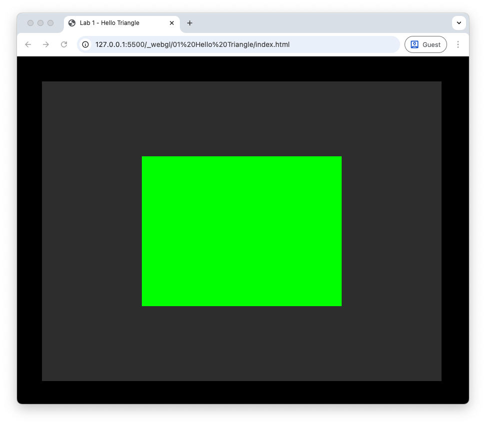
If everything has gone to plan you should be looking at a web browser with a page titled ‘Lab 1 - Basic Shapes’ that displays a canvas element that is 800 pixels wide by 600 pixels high which is a particularly lurid shade of green. The reason for this horrible colour is that we will be clearing the canvas in our WebGL app so if we see this green colour we know something has gone wrong.
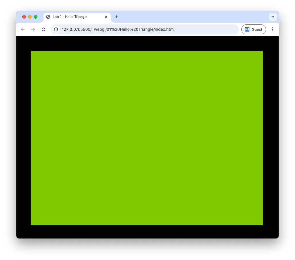
Fig. 1 The lurid green canvas element.#
Task
Inside your 01 Basic Shapes folder, create a JavaScript file basic_shapes.js that contains the following.
// Main function
function main() {

  // Setup WebGL
  const canvas = document.getElementById("canvasId");
  const gl = canvas.getContext('webgl2');
  if (!gl) throw new Error('WebGL not supported');

  gl.viewport(0, 0, canvas.width, canvas.height);
  gl.clearColor(0.2, 0.2, 0.2, 1.0);
  gl.clear(gl.COLOR_BUFFER_BIT);

}

main();
Here we have created our main function main() inside which we have set up the WebGL canvas. Some functions used here are defined below
gl.viewport(0, 0, canvas.width, canvas.height);
Defines the rectangular area of the canvas where rendering will take place that maps to the normalized device co-ordinates (-1 to 1 in the \(x\), \(y\) and \(z\) axes). Here our viewport fills the <canvas> element.
gl.clearColor(0.2, 0.2, 0.2, 1.0);
Defines the background colour. Colours are defined using RGBA values (Red, Green, Blue and Alpha) so here our background is dark grey.
gl.clear(gl.COLOR_BUFFER_BIT);
: Clears the specified buffer, in this case it’s the colour buffer.
Refresh the browser window and you should still see that the horrible lurid green background. But hang on, haven’t we defined our background colour to be dark grey? The reason for this is that we haven’t embedded the JavaScript file into our HTML file.
Task
Edit the <body> tag near the bottom of the index.html file so that it looks like the following.
...
  <body>
    <canvas id="canvasId" width="800px" height="600px"></canvas>
    <script src="basic_shapes.js"></script>
  </body>
...
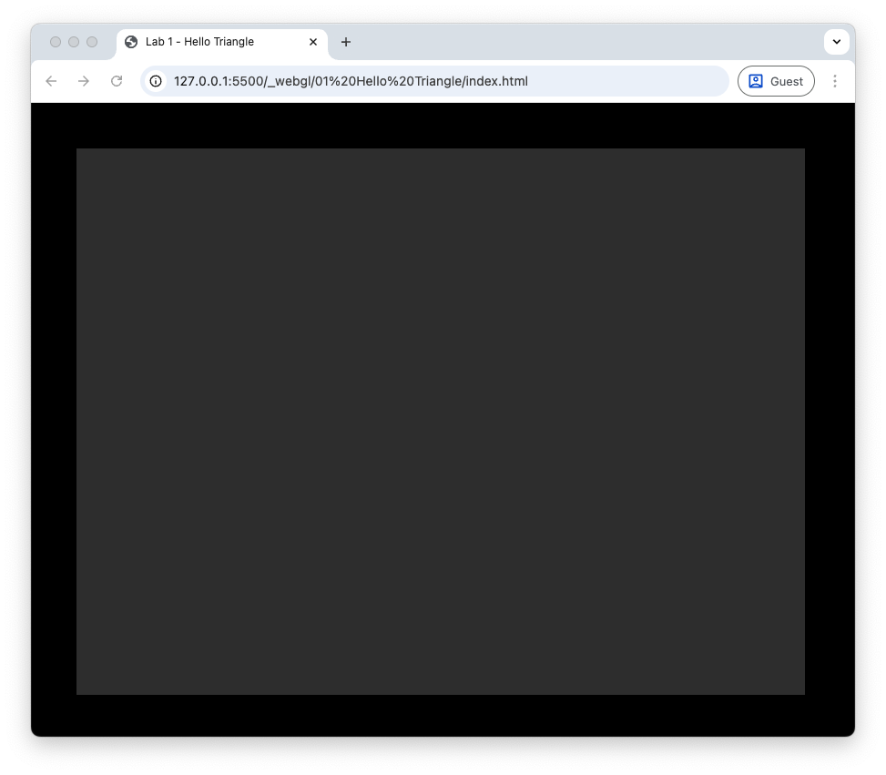
Now if you refresh your browser you should see a dark grey background. If something has gone wrong, and you still see the green background, open up the JavaScript console (if you are using Chrome then press CTRL + SHIFT + J or ⌥ + ⌘ + J on a Mac) and it should give you an indication of what has gone wrong. The life of a graphics programmer is mostly problem-solving and debugging, so get used to doing this.
Draw a Red Triangle#
The first shape we are going to draw with WebGL is a red triangle. We start with a triangle because it is the fundamental building block of modern computer graphics. Every complex 3D model, character, environment, object etc. are ultimately made from many small triangles, and WebGL (like all graphics hardware) is designed to process triangles extremely efficiently.
Triangles are used in computer graphics for several important reasons:
A triangle is always flat. Any three points in space define a single plane, which means a triangle cannot become bent or warped. This makes it reliable for representing surfaces.
They are the simplest possible polygon. With only three vertices, triangles are easy for the GPU to transform, rasterise, and shade. All calculations, such as clipping and interpolation, are simpler with triangles than with more complex shapes.
Graphics hardware is optimized for triangles. Modern GPUs expect triangles as input, and even if you provide quads or other polygons, the hardware will convert them into triangles internally.
Any shape can be built from triangles. Complex models and smooth surfaces can be approximated by dividing them into many small triangles, a process known as tessellation. This allows triangles to represent everything from simple shapes to highly detailed 3D geometry.
Interpolation works cleanly across triangles. Colours, textures, normals, and depth all interpolate smoothly inside a triangle using barycentric co-ordinates, which ensures correct shading and rendering.
Define the Triangle Co-ordinates#
Our triangle will have co-ordinates at \((-0.5, -0.5, 0)\) (lower-left vertex), \((0.5, -0.5, 0)\) (lower-right vertex) and \((0, 0.5, 0)\) (top vertex).

Fig. 2 The vertex co-ordinates for the red triangle example.#
Task
Enter the following just before we clear the canvas.
// Define triangle vertices
const vertices = new Float32Array([
  // x    y    z
  -0.5, -0.5, 0.0, // vertex 0       2
   0.5, -0.5, 0.0, // vertex 1     /   \
   0.0,  0.5, 0.0, // vertex 2    0 --- 1
]);
Here we have defined an array called vertices containing 9 values for the co-ordinates of the 3 triangle vertices. WebGL works best with 32-bit floats, and the default JavaScript float precision is 64-bit, so we use the new Float32Array() command to convert these into 32-bit float array.
Create a Vertex Buffer Object (VBO) for the Triangle#
The data in the vertices array is stored in the CPU (RAM) and not in the GPU. To move data across to the GPU we create a WebGL buffer object known as a Vertex Buffer Object (VBO) and copy in the data.
Task
Enter the following after we have defined the triangle vertices array.
// Create a VBO for the triangle
const vbo = gl.createBuffer();
gl.bindBuffer(gl.ARRAY_BUFFER, vbo);
gl.bufferData(gl.ARRAY_BUFFER, vertices, gl.STATIC_DRAW);
gl.bindBuffer(gl.ARRAY_BUFFER, null);
The commands used here are explained below
const vbo = gl.createBuffer();
Creates a buffer object on the GPU.
gl.bindBuffer(gl.ARRAY_BUFFER, vbo);
Binds our VBO to an array buffer so that WebGL knows where to send the data. The word bind in graphics programming means to make it the currently active resource for a particular purpose so subsequent WebGL operations affect it.
gl.bufferData(gl.ARRAY_BUFFER, vertices, gl.STATIC_DRAW);
Copies the data from the vertices array into the VBO which is the currently bound buffer. The gl.STATIC_DRAW input is a performance hint to WebGL, here we are saying that that triangle vertices will not change.
gl.bindBuffer(gl.ARRAY_BUFFER, null);
Here we unbind the current array buffer, so no subsequent commands will mistakenly affect it.
Write and Compile the Vertex Shader#
The next step is create a shader program that runs on the GPU and uses WebGL to determine which pixels on the display are to be rendered and in what colour. This shader program comprises two separate programs known as “shaders”: the vertex shader and the fragment shader. Shaders are written in GLSL (webGL Shader Language) which is similar to C.
The vertex shader is called once for each vertex and transforms the vertex co-ordinates from model space (the local object co-ordinates) to the clip space that defines the region that is displayed on the canvas. We have defined our triangle using co-ordinates between \(-1\) and \(1\), so they are already in clip space and our vertex shader just needs to output each vertex. The shader code for a simple vertex shader is
#version 300 es
precision mediump float;

in vec3 aPosition;

void main() {
  gl_Position = vec4(aPosition, 1.0);
}
This code is explained below
#version 300 es – Tells the shader we are using GLSL ES 3.00, the shader language used with WebGL 2.0.
precision mediump float; – Sets the default float precision to medium (16-bit).
in vec3 aPosition; – Tells the shader that we are inputting a 3-element vector for the vertex position (the a in aPosition is short for attribute).
gl_Position = vec4(aPosition, 1.0); – Outputs a 4-element vector for the clip space co-ordinates of the vertex (there reason why it’s a 4-element vector will be covered later when we look at transformations). The gl_Position variable is a required output of every vertex shader.
The simplest way of entering shader code into our JavaScript file is to define it as a multiline string.
Task
Add the following at the top of the basic_shapes.js file. Note the use of backticks `...` to define the string using a literal so that we can use a multiline string.
// Define vertex shader
const vertexShaderSource =
`#version 300 es
precision mediump float;

in vec3 aPosition;

void main() {
  gl_Position = vec4(aPosition, 1.0);
}`;
Now add the following after we have set up the WebGL canvas.
// Compile vertex shader
const vertexShader = gl.createShader(gl.VERTEX_SHADER);
gl.shaderSource(vertexShader, vertexShaderSource);
gl.compileShader(vertexShader);

if (!gl.getShaderParameter(vertexShader, gl.COMPILE_STATUS)) {
  console.log(`Error compiling vertex shader:\n`, gl.getShaderInfoLog(vertexShader));
  gl.deleteShader(vertexShader);
}
As well as defining a string for the vertex shader code, we then create a vertex shader object, attach the shader code to it and compile it. There’s no easy way to check for errors in shader code, so it is good practice to do a check to see if it has compiled ok, if not a message is logged to the console.
Write and Compile the Fragment Shader#
The other shader we need to write is the fragment shader. This takes in information on a fragment that has been identified as being part of the primitive (i.e., triangle) and determines the colour that it will be rendered. We are going to render all fragments in the triangle as red, so the fragment shader code is as follows.
#version 300 es
precision mediump float;

out vec4 fragColour;

void main() {
  fragColour = vec4(1.0, 0.0, 0.0, 1.0);
}
This is similar to the vertex shader with a couple of exceptions. The vertex shader has a required output of gl_Position, so this doesn’t need to be declared, fragment shaders can have a number of outputs, so we need to declare these. Here we have declared an output of a 4-element vector using out vec4 fragColour;. Within the main() function, we set the output vector to \((1, 0, 0, 1)\), i.e., all Red, no Blue and no Green components and the Alpha value is set to 1 so that it is opaque.
Task
Add the following after we have defined the vertex shader.
// Define fragment shader
const fragmentShaderSource =
`#version 300 es
precision mediump float;

out vec4 fragColour;

void main() {
  fragColour = vec4(1.0, 0.0, 0.0, 1.0);
}`;
And add the following after we have compiled the vertex shader.
// Compile fragment shader
const fragmentShader = gl.createShader(gl.FRAGMENT_SHADER);
gl.shaderSource(fragmentShader, fragmentShaderSource);
gl.compileShader(fragmentShader);

if (!gl.getShaderParameter(fragmentShader, gl.COMPILE_STATUS)) {
  console.log(`Error compiling fragment shader:\n`, gl.getShaderInfoLog(fragmentShader));
  gl.deleteShader(fragmentShader);
}
This code is very similar to the one used for the vertex shader. Later we will be using a helper function to compile the shaders.
Link the Shaders into a WebGL Program#
The next step is to create a WebGL program and link the vertex and fragment shader to it. In doing this it manages the inputs and outputs, attributes and uniforms between our two shaders.
Task
Add the following after we have compiled the vertex and fragment shaders.
// Create WebGL shader program and link the vertex and fragment shaders
const program = gl.createProgram();
gl.attachShader(program, vertexShader);
gl.attachShader(program, fragmentShader);
gl.linkProgram(program);

if (!gl.getProgramParameter(program, gl.LINK_STATUS)) {
  console.log(`Failed to link WebGL program : ${gl.getProgramInfoLog(program)}`);
return;
}
The commands used here are similar to those used for the vertex and fragment shader. Rather than compiling a shader we simply link the vertex and fragment shaders into a single WebGL program that we have called program using the gl.linkProgram() function. We have also done a check to see if the linking has been successful.
Draw the Triangle#
So far we have done a fair bit of work creating a buffer object for the triangle vertices, written and compiled the vertex and fragment shader and linked these into a WebGL program. But we haven’t drawn anything yet! To do this we need to tell WebGL which shader program to use, tell it how to interpret the vertex data and then tell it to draw the triangle.
Task
Enter the following after we have created the WebGL shader program.
// Set the shader program
gl.useProgram(program);
The gl.useProgram() function tells WebGL which shader program to use. It will use the currently selected program until told differently by another call to this function.
Earlier we created the VBO in the GPU and copied across our vertex data. We now need to tell WebGL where this data is and how to read it, so it can work its magic with the shaders.
Task
Enter the following after you have set the shader program.
// Tell WebGL how to read data from the vertex buffer
const positionLocation = gl.getAttribLocation(program, "aPosition");
gl.enableVertexAttribArray(0);
gl.bindBuffer(gl.ARRAY_BUFFER, vbo);
gl.vertexAttribPointer(
  positionLocation, // index
  3,                // size
  gl.FLOAT,         // type
  false,            // normalized
  0,                // stride
  0);               // offset
The functions used here are explained below;
const positionLocation = gl.getAttribLocation(program, 'aPosition'); – Gets the location of the aPosition attribute from the WebGL shader program.
gl.enableVertexAttribArray(0); – Enables a vertex attribute with location 0 so that WebGL knows to read data from the VBO and pass it to the vertex shader.
gl.bindBuffer(gl.Array_BUFFER, vbo); – Make the VBO the currently active buffer.
gl.vertexAttribPointer(positionLocation, 3, gl.FLOAT, false, 0, 0); – Tells WebGL how to read the data from the currently bound buffer and pass it to the vertex shader attribution 0. The inputs are explained in the table below.
Input |
Description |
|---|---|
index |
Attribute location. We stored this in the |
size |
Number of components per vertex, We have 3D \((x, y, z)\) co-ordinates, so this is 3. |
type |
Data type. We are using floats. |
normalized |
Whether integer values should be mapped to \([0, 1]\) or \([-1, 1]\). Our vertex co-ordinates are in NDC, so we don’t need to do this. |
stride |
Number of bytes between first attribute of each vertex. Our data is tightly packed, so we can set the stride to 0, if the array buffer contained other data, e.g., colours, then we would need to determine the number of bytes between the first attribute, e.g., the \(x\) co-ordinates. |
offset |
Number of bytes from the start of the buffer the attribute of the first vertex. Our first vertex co-ordinate is the first element in the buffer, so this is 0. |
The last thing we need to do is actually tell WebGL to draw the triangle.
Task
Enter the following after the you have told WebGL how to read the data from the vertex buffer.
// Draw the triangle
gl.drawArrays(gl.TRIANGLES, 0, 3);
The gl.drawArrays() function tells the GPU to draw the primitives. The inputs are the type of primitive (we have a triangle), the index of the first vertex and the number of vertices to draw (we have one triangle, so we want to draw 3 vertices). Refresh your browser window, pray to the programming gods and if everything has gone to plan you should see the red triangle displayed on the canvas.
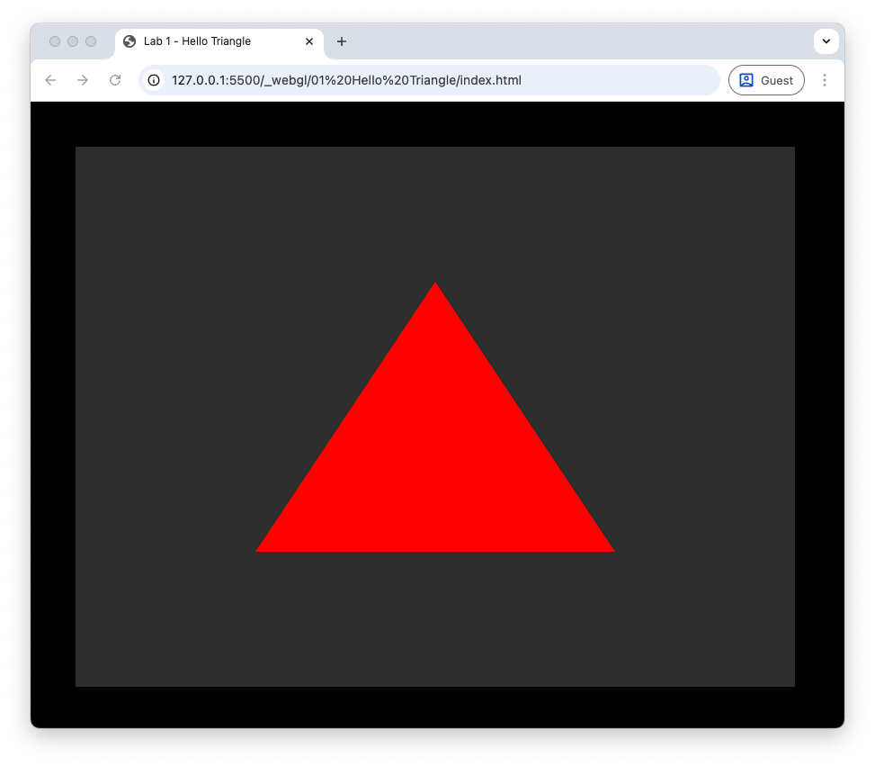
Fig. 3 Hello triangle!#
Steps Used to Draw the Triangle#
Now that we have successfully drawn a triangle, let’s recap the steps we used.
Define the Triangle Co-ordinates - we defined a 9-element array that contained the \((x, y, z)\) co-ordinates of the 3 triangle vertices.
Create a Vertex Buffer Object (VBO) for the Triangle - the buffer objects are stored in the GPU so we needed to create one for the triangle and copy across the triangle co-ordinates so WebGL can work with them.
Write and Compile the Vertex Shader - a vertex shader is used to transform the vertex co-ordinates to the clip space. The output is sent to the WebGL rasteriser that passes the fragment co-ordinates to the fragment shader.
Write and Compile the Fragment Shader - a fragment shader is used to determine the colour that the fragment should be rendered on the display.
Link the Shaders into a WebGL Program - the vertex and fragment shaders are linked into a single program that we tell WebGL to use to draw the triangle.
Draw the Triangle - we need to tell WebGL how to access the data in the triangle buffer and instruct it to draw the triangle.
WebGL Utility Functions#
Looking at our main() function we see that the code to compile and link the shaders is very similar for the vertex and fragment shaders. In the spirit of DRY (Do not Repeat Yourself), we will now write some utility functions to simplify the code.
Task
Create a new JavaScript files called webGLUtils.js within the 01 Basic Shapes folder and enter the following code.
// Initialize WebGL context
function initWebGL(canvas) {
  const gl = canvas.getContext('webgl2') || canvas.getContext('webgl');
  if (!gl) throw new Error('WebGL not supported');

  gl.viewport(0, 0, canvas.width, canvas.height);
  gl.clearColor(0.2, 0.2, 0.2, 1.0);
  gl.clear(gl.COLOR_BUFFER_BIT);

  return gl;
}

// Compile a shader
function compileShader(gl, source, type) {
  const shader = gl.createShader(type);
  gl.shaderSource(shader, source);
  gl.compileShader(shader);

  if (!gl.getShaderParameter(shader, gl.COMPILE_STATUS)) {
    console.error(gl.getShaderInfoLog(shader));
    gl.deleteShader(shader);
    return null;
  }
  return shader;
}

// Create shader program
function createProgram(gl, vertexSrc, fragmentSrc) {
  const vertexShader = compileShader(gl, vertexSrc, gl.VERTEX_SHADER);
  const fragmentShader = compileShader(gl, fragmentSrc, gl.FRAGMENT_SHADER);

  const program = gl.createProgram();
  gl.attachShader(program, vertexShader);
  gl.attachShader(program, fragmentShader);
  gl.linkProgram(program);

  if (!gl.getProgramParameter(program, gl.LINK_STATUS)) {
    console.error(gl.getProgramInfoLog(program));
    gl.deleteProgram(program);
    return null;
  }
  return program;
}
This new file webGLUtils.js is used to contain any utility functions that are required for WebGL. Here we have defined the functions initWebGL() which sets up the WebGL canvas and returns a gl object, compileShader() which compiles a vertex or fragment shader, and createProgram() links the shaders to create a WebGL program. If you compare them to the equivalent code in the main() function you can see that they are quite similar. To enable our main file to use these functions we also need to add webGLUtils.js to the index.html file using a script tag.
Task
Add the following just before the basic_shapes.js script tag.
<script src="webGLUtils.js"></script>
We can now tidy up the main() function and make a call to out new createprogram() function.
Task
Comment out (or delete) the code used to set up the WebGL canvas and replace it with the following.
// Setup WebGL
const canvas = document.getElementById("canvasId");
const gl = initWebGL(canvas);
Comment out (or delete) the code used to compile and link the shaders and replace it with the following.
// Create WebGL program
const program = createProgram(gl, vertexShaderSource, fragmentShaderSource);
Refresh your browser window and if everything has gone to plan you should see your red triangle as before. This effort is not wasted, we can now easily create WebGL programs from the source code without lots of copying and pasting of existing code. We will be using the webGLUtils.js and other JavaScript files to help organize and simplify our code in the future.
Colours#
So we are able to draw a triangle using WebGL of a single colour. Whilst this is awesome, wouldn’t it be better if we were able to draw triangles using different colours? We will now see how we can add colour data to each vertex and use these in our shaders.
Vertex and Fragment Shaders#
Our current vertex shader simply takes in an input of a 3-element vector containing the \((x, y, z)\) vertex co-ordinates and outputs a 4-element vector of these co-ordinates to the fragment shader. The vertex co-ordinates are outputted using the gl_Position variable which is a required output and is not specifically declared. To add colour data to our co-ordinates we need to declare a second 3-element input vector for the attribute colour as well as an output vector for the vertex colour. So our vertex shader is
#version 300 es
precision mediump float;

in vec3 aPosition;
in vec3 aColour;

out vec3 vColour;

void main() {
  gl_Position = vec4(aPosition, 1.0);

  // Output vertex colour
  vColour = aColour;
}
As for the fragment shader, we will simply output the colour data of the vertex. Our current fragment shader does not have an input declared because it expects gl_Position by default, so we need to add an input declaration for the vertex colour outputted by the vertex shader and use this to create the 4-element RGBA output vector.
#version 300 es
precision mediump float;

in vec3 vColour;

out vec4 fragColour;

void main() {
  fragColour = vec4(vColour, 1.0);
}
Task
Edit the vertex shader code at the top of the basic_shapes.js file so that is contains the modified vertex and fragment shaders shown above.
Vertex Colours#
To add colour data to the triangle vertices we add 3 more float values for the red, green and blue colours to the vertices array.
Task
Amend the vertices array so that it looks like the following.
// Define triangle vertices
const vertices = new Float32Array([
 // x     y    z      r    g    b
 -0.5, -0.5, 0.0,    1.0, 0.0, 0.0, // vertex 0       2
  0.5, -0.5, 0.0,    0.0, 1.0, 0.0, // vertex 1     /   \
  0.0,  0.5, 0.0,    0.0, 0.0, 1.0, // vertex 2    0 --- 1
]);
Here we have specified vertex 0 is pure red, vertex 1 is pure green and vertex 2 is pure blue. If you refresh your web browser you should see that the red triangle is black and skewed, where it appears that the top vertex has been moved to the right-hand edge of the canvas (Oops, something has gone wrong.). The reason why its skewed is that when we told WebGL how to read the vertex buffer using gl.vertexAttribPointer(colourLocation, 3, gl.FLOAT, false, 0, 0);. This means that WebGL is expected no gaps between the vertex co-ordinate data since the stride input (the second to last input) is 0, so it thinks the 3 vertex co-ordinates are \((-0.5, -0.5, 0)\), \((1, 0, 0)\) and \((0.5, -0.5, 0)\).
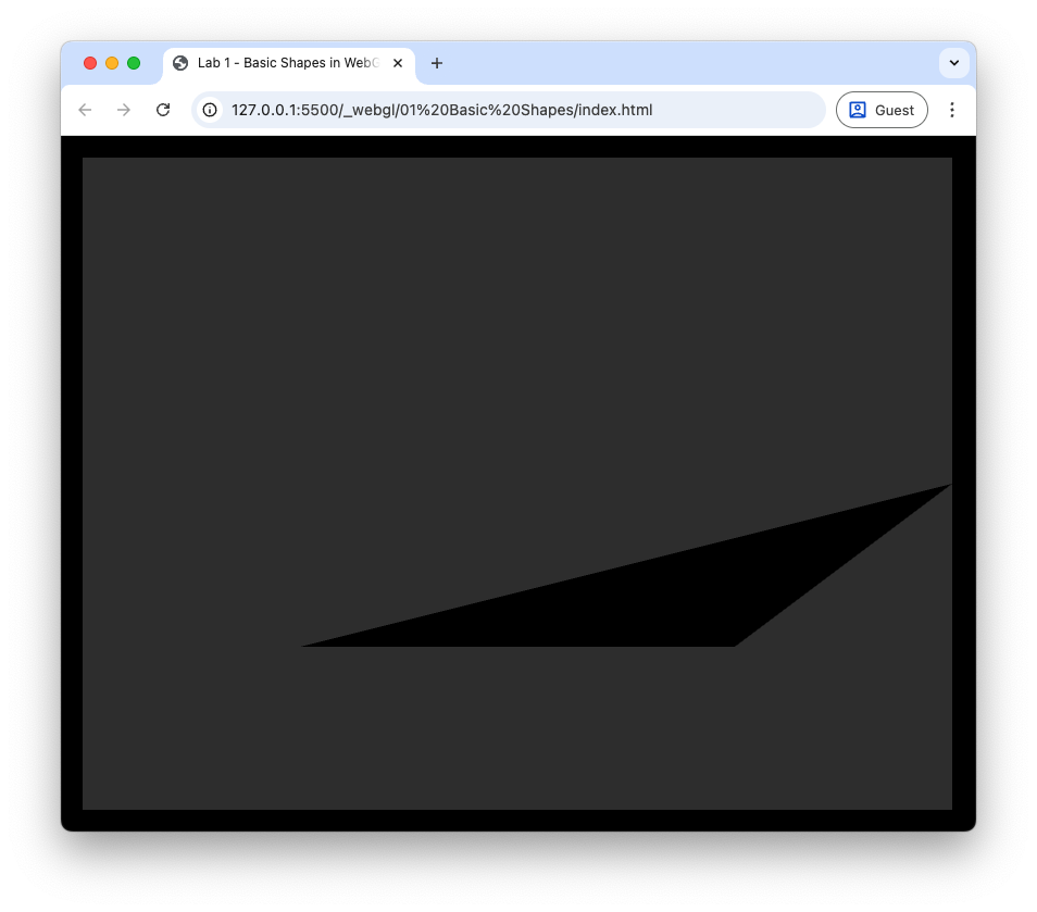
Fig. 4 Oops, something has gone wrong.#
This is where the stride input for the gl.vertexAttribPointer() function comes in. Stride is the number of bytes from the start of the attribute (in our case the \(x\) vertex co-ordinate) for one vertex to the start of the same attribute of the next vertex. We added 3 floats for the RGB data, so our stride is the number of bytes used to store 6 float values, i.e., 3 for the \((x, y, z)\) values and 3 for the RGB values.

Fig. 5 The stride and offset of a vertex array.#
Task
Change the gl.vertexAttribPointer(); function so that it looks like the following.
gl.vertexAttribPointer(
  positionLocation,                    // index
  3,                                   // size
  gl.FLOAT,                            // type
  false,                               // normalized
  6 * Float32Array.BYTES_PER_ELEMENT,  // stride
  0                                    // offset
);
Refresh your browser, and you should see that the triangle vertices has returned to its previous state, but it’s still black (Fig. 6). The reason for this is that we have not yet told WebGL about our new vertex colours. To do this we get the location of the aColour attribute from the vertex shader, enable the attribute array and point WebGL to where it can find the colour data.
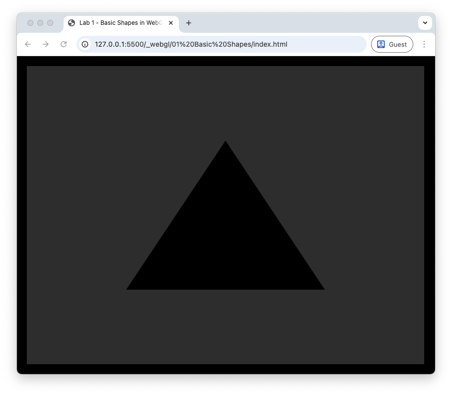
Fig. 6 Sorted the vertex co-ordinates but not the colour.#
Task
Enter the following code after we told WebGL how to read the co-ordinate data.
const colourLocation = gl.getAttribLocation(program, 'aColour');
gl.enableVertexAttribArray(colourLocation);
gl.vertexAttribPointer(
  colourLocation,                      // index
  3,                                   // size
  gl.FLOAT,                            // type
  false,                               // normalized
  6 * Float32Array.BYTES_PER_ELEMENT,  // stride
  3 * Float32Array.BYTES_PER_ELEMENT   // offset
);
Note that here the offset value is 3 times of the number of bytes used to store a 32-bit float. This is because the colour data comes after the 3 floats for the co-ordinate values.
Refresh your browser you should see the triangle in all its glorious colourfulness.
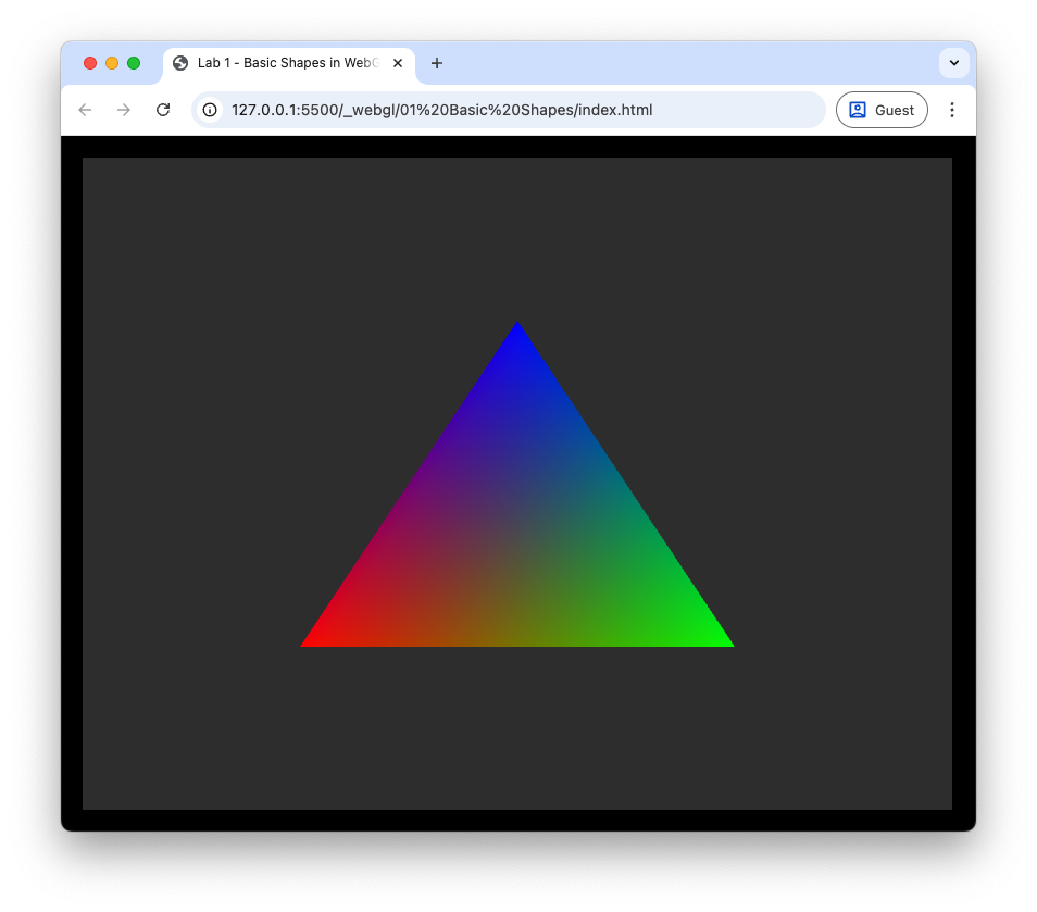
Fig. 7 Hello colourful triangle!#
You can see that the 3 triangle vertices are red, green and blue going anti-clockwise from the bottom-left vertex. The colour of the pixels across the interior of the triangle have been interpolated by the rasteriser so that we have a smooth transition of colours.
More Shapes#
To keep our colourful triangle company we are going to introduce another shape, a square, to our scene. In most graphics applications shapes are constructed using triangle primitives. Triangles are the simplest 2D shape and all other shapes are constructed using triangles. So to construct a square we need two triangles.
Task
Enter the following code after we defined the triangle vertex buffer.
// Define square vertices
const squareVertices = new Float32Array([
  // x  y    z       r    g    b
  0.5, 0.2, 0.0,    1.0, 0.0, 0.0, // vertex 0     3 -- 2
  0.8, 0.2, 0.0,    0.0, 1.0, 0.0, // vertex 1     |  / |
  0.8, 0.6, 0.0,    0.0, 0.0, 1.0, // vertex 2     | /  |
  0.5, 0.2, 0.0,    1.0, 0.0, 0.0, // vertex 0     0 -- 1
  0.8, 0.6, 0.0,    0.0, 0.0, 1.0, // vertex 2
  0.5, 0.6, 0.0,    1.0, 1.0, 1.0, // vertex 3
]);

// Create VBO for the square
const squareVbo = gl.createBuffer();
gl.bindBuffer(gl.ARRAY_BUFFER, squareVbo);
gl.bufferData(gl.ARRAY_BUFFER, squareVertices, gl.STATIC_DRAW);
gl.bindBuffer(gl.ARRAY_BUFFER, null);
Here we have defined the co-ordinates and colours for vertices of a square. We are using 2 triangles to construct the square, so we have 6 vertices in total. Like with the triangle, we have also created a vertex buffer for the square and copied the data across to the GPU. We now need to tell WebGL how to read the square vertex buffer and to draw the 2 triangles that make up the square.
Task
Enter the following code after we have drawn the triangle.
// Tell WebGL how to read data from the square vertex buffer
gl.bindBuffer(gl.ARRAY_BUFFER, squareVbo);
gl.enableVertexAttribArray(positionLocation);
gl.vertexAttribPointer(positionLocation, 3, gl.FLOAT, false, 6 * Float32Array.BYTES_PER_ELEMENT, 0);
gl.enableVertexAttribArray(colourLocation);
gl.vertexAttribPointer(colourLocation, 3, gl.FLOAT, false, 6 * Float32Array.BYTES_PER_ELEMENT, 3 * Float32Array.BYTES_PER_ELEMENT);

// Draw the square
gl.drawArrays(gl.TRIANGLES, 0, 6);
This is very similar to what we did for the triangle object, i.e., we bind the vertex buffer for the square, enable the vertex attribute array and tell WebGL where the data is. Note that we already know the location of the position and colour attributes. Since we are drawing two squares, we change the 3 to a 6 in the gl.drawArrays() function.
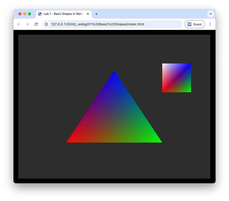
Fig. 8 Our triangle now has a friend.#
Vertex Array Objects (VAO)#
You may have noticed that telling WebGL how to read the VBOs for both the triangle and square objects required repetition of code. Every time we draw a different object we are repeating this code, with just 2 objects this isn’t too bad, but when we are dealing with hundreds of objects it will become unmanageable. A Vertex Array Object (VAO) is a WebGL object that stores all the state related to the vertex, i.e., vertex attributes and bindings to attribute locations, so that once it is set up we only need a single block of code to bind the VAO and draw the object.
We are going to create a utility function to create a VAO.
Task
Enter the following function definition to the webGLUtils.js file.
// Create VAO
function createVao(gl, program, vertices) {

  // Create VAO
  const vao = gl.createVertexArray();
  gl.bindVertexArray(vao);

  // Create VBO
  const vbo = gl.createBuffer();
  gl.bindBuffer(gl.ARRAY_BUFFER, vbo);
  gl.bufferData(gl.ARRAY_BUFFER, vertices, gl.STATIC_DRAW);

  // Position attribute
  const stride = 6 * Float32Array.BYTES_PER_ELEMENT;
  const positionLocation = gl.getAttribLocation(program, "aPosition");
  gl.enableVertexAttribArray(positionLocation);
  gl.vertexAttribPointer(positionLocation, 3, gl.FLOAT, false, stride, 0);

  // Colour attribute
  let offset = 3 * Float32Array.BYTES_PER_ELEMENT;
  const colourLocation = gl.getAttribLocation(program, "aColour");
  gl.enableVertexAttribArray(colourLocation);
  gl.vertexAttribPointer(colourLocation, 3, gl.FLOAT, false, stride, offset);

  // Unbind VAO
  gl.bindVertexArray(null);

  return vao;
}
Here we create a VAO using the gl.createVertexArray() function and bind it. Then we create the VBO and tell WebGL how to access the data using the same commands as before. The last thing we do before returning the VAO is to unbind it so that we don’t accidentally make changes with subsequent code.
Task
Delete (or comment out) any commands used to create VBOs for the triangle and square as well as commands used to tell WebGL how to read the data.
The use the following commands to draw the triangle and square.
// Draw triangle
gl.bindVertexArray(triangleVAO);
gl.drawArrays(gl.TRIANGLES, 0, 3);

// Draw square
gl.bindVertexArray(squareVAO);
gl.drawArrays(gl.TRIANGLES, 0, 6);
Your main() function should not look like the following.
function main() {

  // Setup WebGL
  const canvas = document.getElementById("canvasId");
  const gl = initWebGL(canvas);

  // Create WebGL program
  const program = createProgram(gl, vertexShaderSource, fragmentShaderSource);

  // Set the shader program
  gl.useProgram(program);

  // Define triangle vertices
  const vertices = new Float32Array([
    // x     y    z      r    g    b
    -0.5, -0.5, 0.0,    1.0, 0.0, 0.0, // vertex 0       2
     0.5, -0.5, 0.0,    0.0, 1.0, 0.0, // vertex 1     /   \
     0.0,  0.5, 0.0,    0.0, 0.0, 1.0, // vertex 2    0 --- 1
  ]);

  // Define square vertices
  const squareVertices = new Float32Array([
    // x  y    z       r    g    b
    0.5, 0.2, 0.0,    1.0, 0.0, 0.0, // vertex 0     3 -- 2
    0.8, 0.2, 0.0,    0.0, 1.0, 0.0, // vertex 1     |  / |
    0.8, 0.6, 0.0,    0.0, 0.0, 1.0, // vertex 2     | /  |
    0.5, 0.2, 0.0,    1.0, 0.0, 0.0, // vertex 0     0 -- 1
    0.8, 0.6, 0.0,    0.0, 0.0, 1.0, // vertex 2
    0.5, 0.6, 0.0,    1.0, 1.0, 1.0, // vertex 3
  ]);

  // Create VAOs
  const triangleVao = createVao(gl, program, vertices);
  const squareVao = createVao(gl, program, squareVertices);

  // Draw the triangle
  gl.bindVertexArray(triangleVao);
  gl.drawArrays(gl.TRIANGLES, 0, 3);

  // Draw the square
  gl.bindVertexArray(squareVao);
  gl.drawArrays(gl.TRIANGLES, 0, 6);
}
Refresh your web browser, and you should see that we still have the colourful triangle and square, good news as it means the VAOs are working.
Element Buffer Objects#
To add the square to our scene we used 6 vertices, 3 for each of the triangle. Two of these vertices, 0 and 2, are shared by both triangles, so we are using more memory than required. To avoid redundant vertex data being created and using up memory, we can define an array of the indices for each triangle which maps to the vertex data. The buffer that we use to store the indices is called the Element Buffer Object (EBO).
Task
Add the following arrays after the square vertices have been defined.
// Define triangle indices
const indices = new Uint16Array([
 0, 1, 2
]);

// Define square indices
const squareIndices = new Uint16Array([
 0, 1, 2,  // lower-right triangle
 0, 2, 3,  // upper-left triangle
]);
Here we have defined two 16-bit integer arrays for the indices of the triangle and square. We now need to update the createVao() utility function to use these index arrays.
Task
Add an input for the index array in the createVao() function.
// Create VAO
function createVao(gl, program, vertices, indices) {
And add the following code after we create the VBO.
// Create EBO
const ebo = gl.createBuffer();
gl.bindBuffer(gl.ELEMENT_ARRAY_BUFFER, ebo);
gl.bufferData(gl.ELEMENT_ARRAY_BUFFER, indices, gl.STATIC_DRAW);
These commands a similar those used for the vertex buffer. Note that here we need to specify that we have an element array buffer instead of a standard array buffer. The index buffer does not contain any data specific to the vertices, so we don’t need to add it to a VAO, instead we bind it whilst the VAO is bound and WebGL ‘remembers’ it as part of the VAO’s state.
Finally, we need to tell WebGL that our data for the square is defined using indices, so we need to change the draw commands.
Task
Replace the gl.drawArrays() command for the square with the following.
// Draw the triangle
gl.bindVertexArray(triangleVao);
gl.drawElements(gl.TRIANGLES, 3, gl.UNSIGNED_SHORT, 0);

// Draw the square
gl.bindVertexArray(squareVao);
gl.drawElements(gl.TRIANGLES, 6, gl.UNSIGNED_SHORT, 0);
Refresh your browser, and you should see that the output has not changed, but we can now draw different objects easily by binding its VAO and using the draw command.
Exercises#
Change the vertex shader so that the following results are achieved.
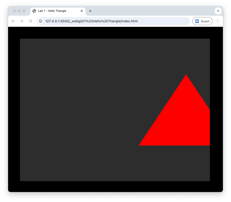
(a) The triangle is shifted by 0.75 to the right.
Hint
We can access individual elements of the aPosition vectors using aPosition.x, aPosition.y and aPosition.z – this is known as swizzling.
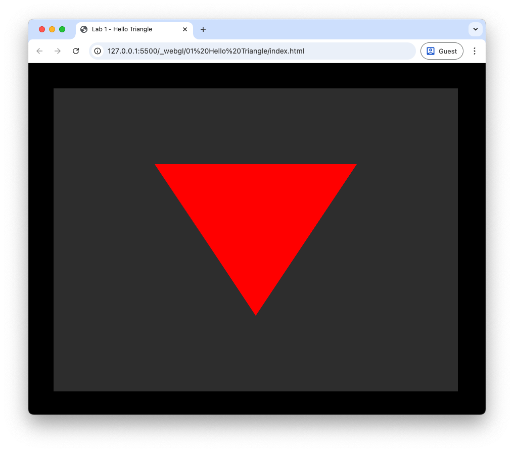
(b) The triangle is drawn upside-down.
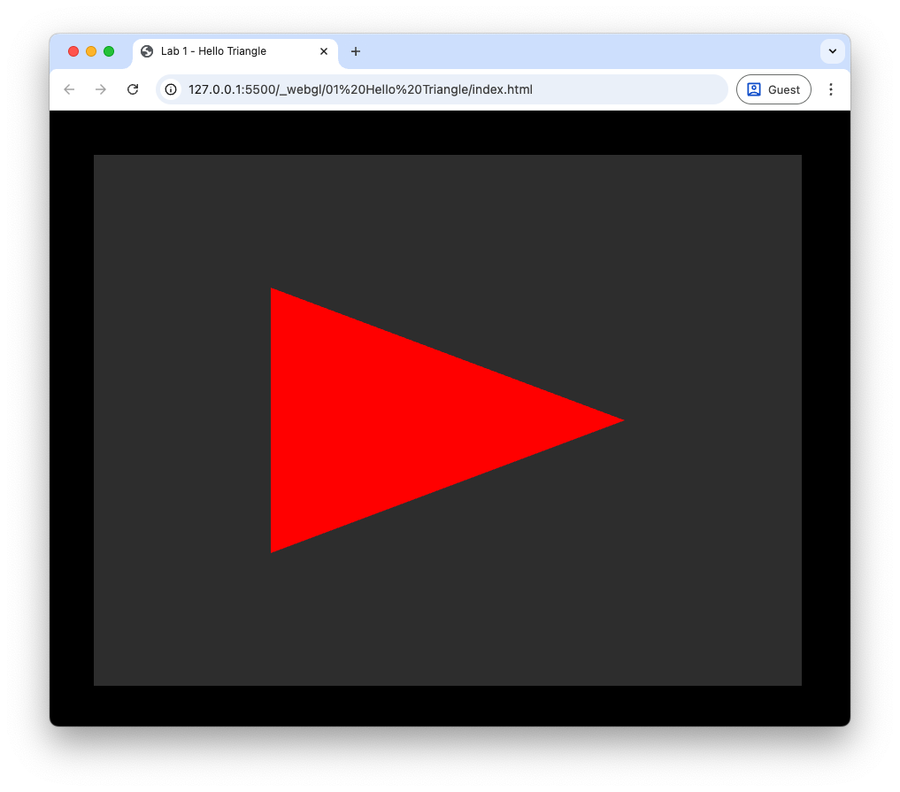
(c) The \(x\) and \(y\) co-ordinates are swapped.
Use two triangles to draw a green rectangle with lower-left vertex at \((-0.5, -0.5, 0)\) and the upper-right vertex at \((0.5, 0.5, 0)\).
Use triangles to draw a blue hexagon.
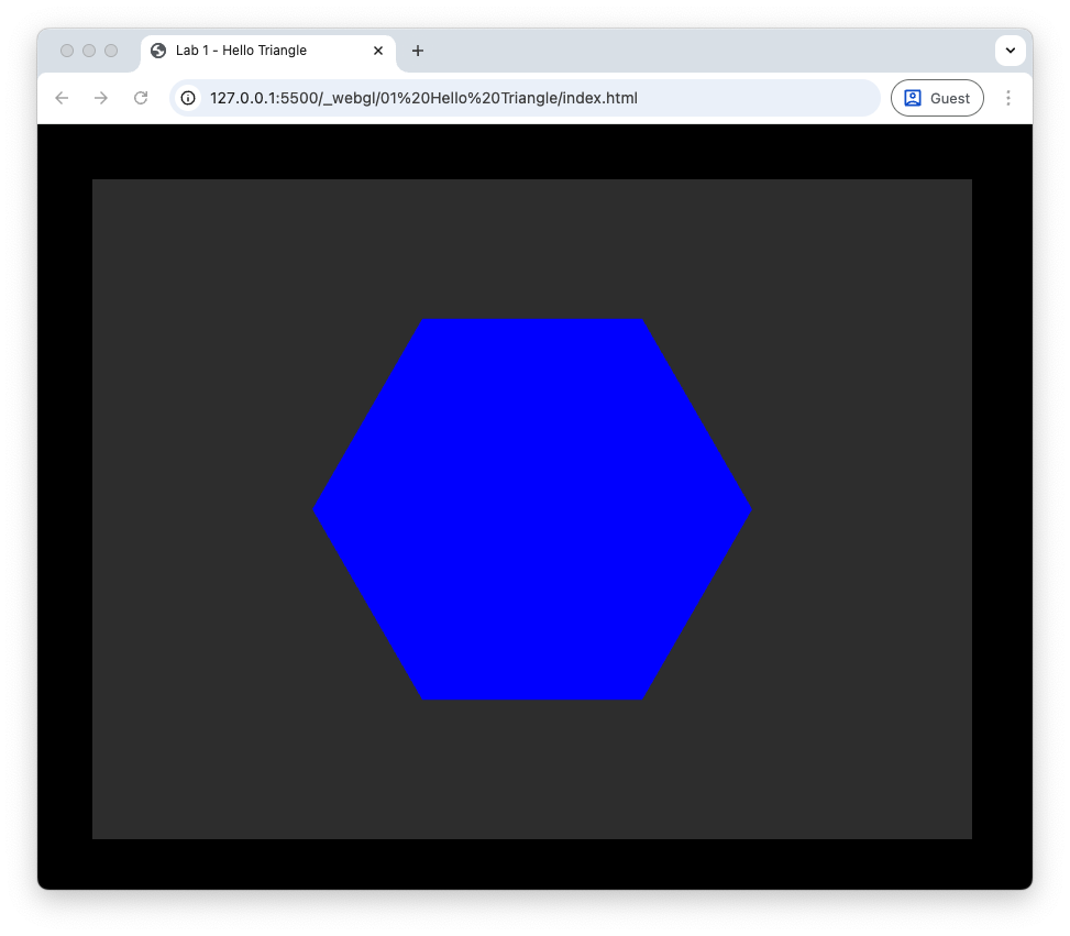
Hint
We can draw a hexagon using 6 triangles where each triangle has one vertex at \((0,0,0)\) and two outer vertices that lie on the circumference of a circle.

The \(x\) and \(y\) vertices of the two outer vertices are
where \(r\) is the radius and the angles \(\theta_i\) and \(\theta_{i+1}\) are calculated using
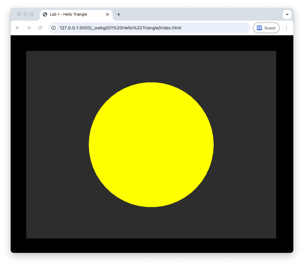
Use lots of triangles to draw a yellow circle.